disk array configurations. By using a
available to the system.
multiplexers daisy chained together.
bypassed.鈥?When the 鈥渄isk in loop鈥?/div>
mode is selected, the loop goes into
and out of the disk drive at that
port. For example, data goes from
the HDMP-0450鈥檚 TO_NODE[n]卤
differential output pins to the Disk
Drive Transceiver IC鈥檚 (e.g., an
HDMP-1636A) Rx differential input
pins. Data from the Disk Drive
Transceiver IC鈥檚 Tx differential
outputs goes to the HDMP-0450鈥檚
FM_NODE[n]卤 differential input
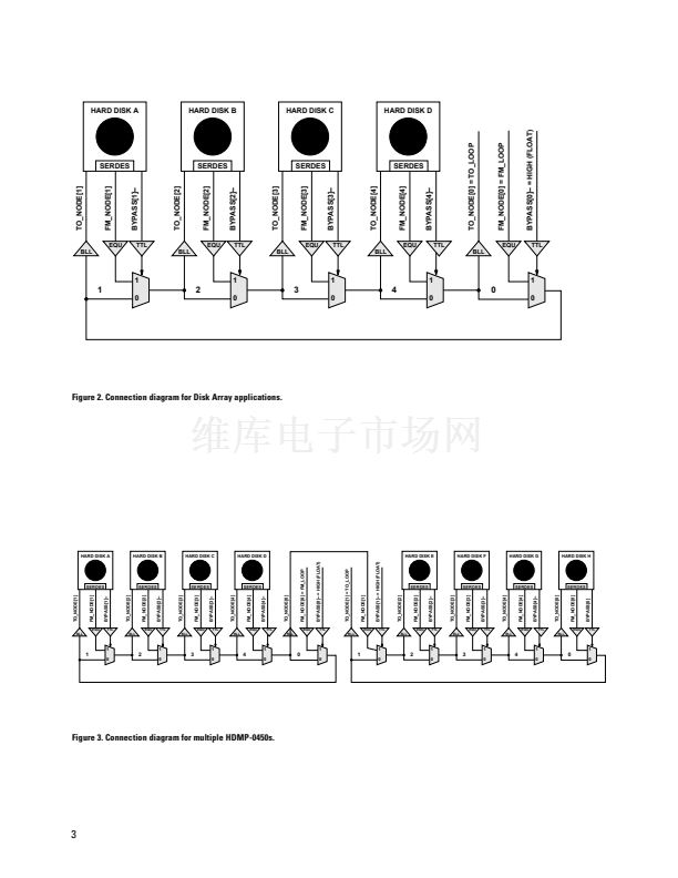
pins. Figure 2 shows connection
diagrams for disk drive array
applications. When the 鈥渄isk
bypassed鈥?mode is selected, the
disk drive is either absent or
nonfunctional and the loop
bypasses the hard disk.
The 鈥渄isk bypassed鈥?mode is
enabled by pulling the BYPASS[n]-
pin low. Leave BYPASS[n]-
floating to enable the 鈥渄isk in
loop鈥?mode. HDMP-0450s may be
cascaded with other members of
the HDMP-04XX/HDMP-05XX
family through the appropriate
FM_NODE[n]卤 and
TO_NODE[n]卤 pins to
accommodate any number of hard
disks (see Figure 3). The unused
cells in the HDMP-0450 may be
bypassed by using pulldown
resistors on the BYPASS[n]- pins
for these cells.
An HDMP-0450 may also be
configured as five 1:1 buffers, as
two 2:1 multiplexers, or as two
1:2 buffers.
鈥?Supports 1.25 GBd Gigabit Ethernet
(GE) operation
鈥?Quad PBC in one package
鈥?Signal detect on FM_NODE[0] input
鈥?Equalizers on all inputs
鈥?High speed LVPECL I/O
鈥?Buffered Line Logic (BLL) outputs
(no external bias resistors required)
鈥?0.5 W typical power at V
CC
= 3.3 V
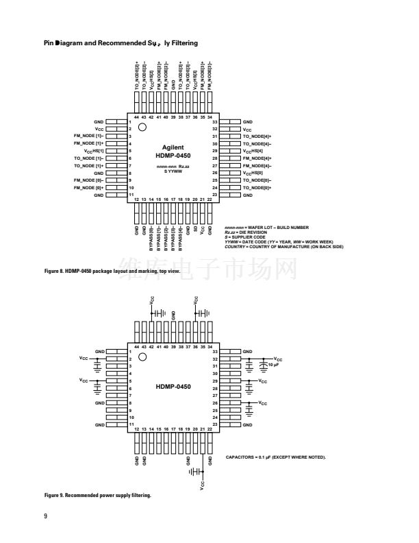
鈥?44 Pin, 10 mm, low-cost plastic QFP
package
Applications
鈥?RAID, JBOD, BTS cabinets
鈥?Two 2:1 muxes
鈥?Two 1:2 buffers
鈥?1 => N gigabit serial buffer
鈥?N => 1 gigabit serial mux
HDMP-0450
CAUTION:
As with all semiconductor ICs, it is advised that normal static precautions be taken in the handling
and assembly of this component to prevent damage and/or degradation which may be induced by electrostatic
discharge (ESD).


 1
1
 2
2
 3
3
 4
4
 5
5
 6
6
 7
7
 8
8
 9
9
 10
10
