鈥?/div>
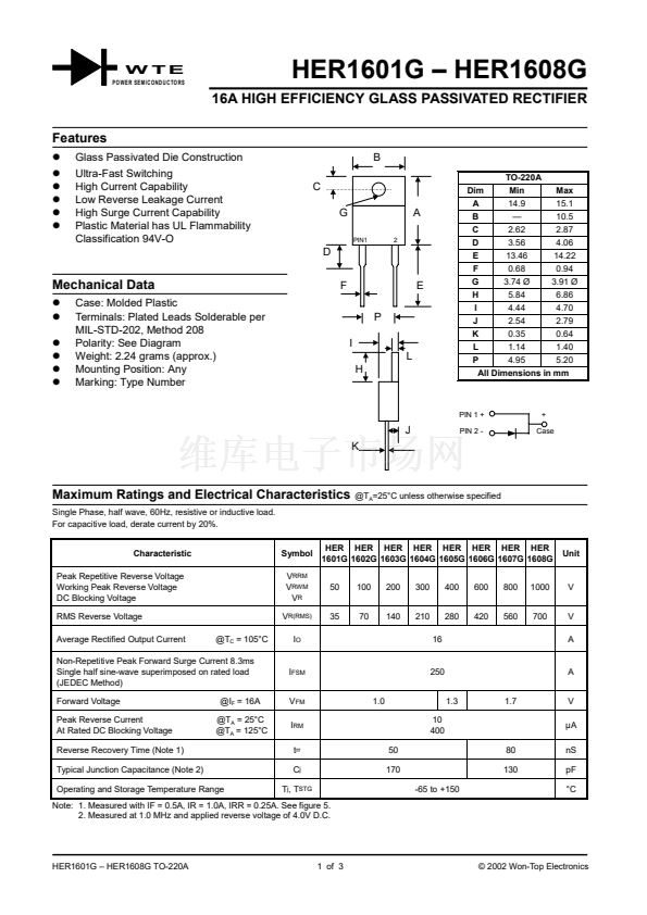
10.5
C
2.62
2.87
D
3.56
4.06
E
13.46
14.22
F
0.68
0.94
G
3.74 脴
3.91 脴
H
5.84
6.86
I
4.44
4.70
J
2.54
2.79
K
0.35
0.64
L
1.14
1.40
P
4.95
5.20
All Dimensions in mm
A
D
Mechanical Data
!
!
!
!
!
!
Case: Molded Plastic
Terminals: Plated Leads Solderable per
MIL-STD-202, Method 208
Polarity: See Diagram
Weight: 2.24 grams (approx.)
Mounting Position: Any
Marking: Type Number
F
P
I
L
H
E
PIN 1 +
+
Case
J
K
PIN 2 -
Maximum Ratings and Electrical Characteristics
Single Phase, half wave, 60Hz, resistive or inductive load.
For capacitive load, derate current by 20%.
@T
A
=25掳C unless otherwise specified
Characteristic
Peak Repetitive Reverse Voltage
Working Peak Reverse Voltage
DC Blocking Voltage
RMS Reverse Voltage
Average Rectified Output Current
@T
C
= 105掳C
Symbol
V
RRM
V
RWM
V
R
V
R(RMS)
I
O
HER HER HER HER HER HER HER HER
1601G 1602G 1603G 1604G 1605G 1606G 1607G 1608G
50
35
100
70
200
140
300
210
16
400
280
600
420
800
560
1000
700
Unit
V
V
A
Non-Repetitive Peak Forward Surge Current 8.3ms
Single half sine-wave superimposed on rated load
(JEDEC Method)
Forward Voltage
Peak Reverse Current
At Rated DC Blocking Voltage
Reverse Recovery Time (Note 1)
Typical Junction Capacitance (Note 2)
Operating and Storage Temperature Range
@I
F
= 16A
@T
A
= 25掳C
@T
A
= 125掳C
I
FSM
V
FM
I
RM
t
rr
C
j
T
j
, T
STG
50
170
1.0
250
1.3
10
400
80
130
-65 to +150
1.7
A
V
碌A
nS
pF
掳C
Note: 1. Measured with IF = 0.5A, IR = 1.0A, IRR = 0.25A. See figure 5.
2. Measured at 1.0 MHz and applied reverse voltage of 4.0V D.C.
HER1601G 鈥?HER1608G TO-220A
1 of 3
漏 2002 Won-Top Electronics


 1
1
 2
2
 3
3
