High surge current capability.
Reliable construction technique.
Ideal for printed circuit board.
鈥?/div>
~
~ +
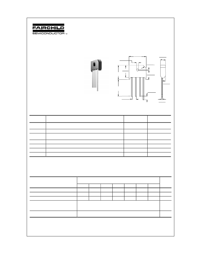
0.405(10.3)
0.165(4.2)
0.150(3.8)
KBU
1.0(2.54)
MIN
0.260(6.8)
0.180(4.5)
0.220(5.6)
8.0 Ampere Silicon Bridge Rectifiers
Absolute Maximum Ratings*
Symbol
I
O
i
f(surge)
P
D
R
胃JA
R
胃JL
T
stg
T
J
Average Rectified Current
@ T
A
= 50掳C
Peak Forward Surge Current
Total Device Dissipation
Derate above 25掳C
Thermal Resistance, Junction to Ambient,** per leg
Thermal Resistance, Junction to Lead,** per leg
Storage Temperature Range
Operating Junction Temperature
T
A
= 25掳C unless otherwise noted
0.180(4.6)
0.052(1.3)
0.048(1.2)
Dimensions are in: inches (mm)
Parameter
Value
8.0
300
6.9
55
18
3.0
-55 to +150
-55 to +150
Units
A
A
W
mW/掳C
掳C/W
掳C/W
掳C
掳C
*
These ratings are limiting values above which the serviceability of any semiconductor device may be impaired.
**
Device mounted on PCB with 0.375 " (9.5 mm) lead length and 0.5 x 0.5" (13 x 13 mm) copper pads.
Electrical Characteristics
Parameter
8A
Peak Repetitive Reverse Voltage
Maximum RMS Bridge Input Voltage
DC Reverse Voltage
(Rated V
R
)
Maximum Reverse Leakage,
total bridge @ rated V
R
T
A
= 25掳C
T
A
= 100掳C
Maximum Forward Voltage Drop,
per bridge
@ 8.0 A
50
35
50
T
A
= 25掳C unless otherwise noted
Device
8B
100
70
100
8D
200
140
200
8G
400
280
400
10
500
1.0
8J
600
420
600
8K
800
560
800
8M
1000
700
1000
Units
V
V
V
碌A
碌A
V
漏1999
Fairchild Semiconductor Corporation
KBU8A-KBU8M, Rev. A


 1
1
 2
2
 3
3
