鈥?/div>
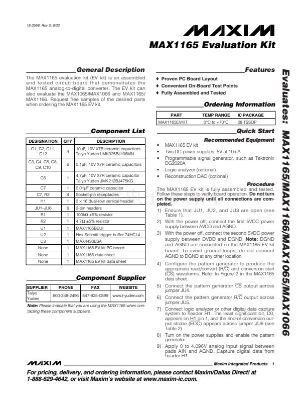
MAX1165 EV kit
Two DC power supplies, 5V at 10mA
Programmable signal generator, such as Tektronix
DG2020A
Logic analyzer (optional)
Reconstruction DAC (optional)
Procedure
The MAX1165 EV kit is fully assembled and tested.
Follow these steps to verify board operation.
Do not turn
on the power supply until all connections are com-
pleted.
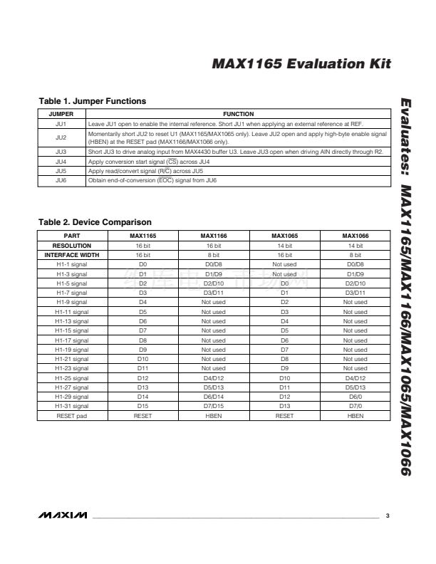
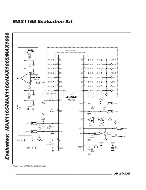
1) Ensure that JU1, JU2, and JU3 are open (see
Table 1).
2) With the power off, connect the first 5VDC power
supply between AVDD and AGND.
3) With the power off, connect the second 5VDC power
supply between DVDD and DGND.
Note:
DGND
and AGND are connected on the MAX1165 EV kit
board. To avoid ground loops, do not connect
AGND to DGND at any other location.
4) Configure the pattern generator to produce the
appropriate read/convert (R/C) and conversion start
(CS) waveforms. Refer to Figure 2 in the MAX1165
data sheet.
5) Connect the pattern generator
CS
output across
jumper JU4.
6) Connect the pattern generator R/C output across
jumper JU5.
7) Connect logic analyzer or other digital data capture
system to header H1. The least significant bit, D0,
appears on H1 pin 1, and the end-of-conversion out-
put strobe (EOC) appears across jumper JU6 (see
Table 2).
8) Turn on the power supplies and enable the pattern
generator.
9) Apply 0 to 4.096V analog input signal between
pads AIN and AGND. Capture digital data from
header H1.
1
Component Supplier
SUPPLIER
Taiyo
Yuden
PHONE
FAX
WEBSITE
www.t-yuden.com
800-348-2496 847-925-0899
Note:
Please indicate that you are using the MAX1165 when con-
tacting these component suppliers.
________________________________________________________________
Maxim Integrated Products
For pricing, delivery, and ordering information, please contact Maxim/Dallas Direct! at
1-888-629-4642, or visit Maxim鈥檚 website at www.maxim-ic.com.


 1
1
 2
2
 3
3
 4
4
 5
5
