19-1160; Rev 1; 8/97
MAX1241 Evaluation System/Evaluation Kit
________________General Description
The MAX1241 evaluation kit (EV kit) is an assembled
and tested PC board that demonstrates the 3V, 12-bit
MAX1241 analog-to-digital converter.
The MAX1241 evaluation system (EV system) is a com-
plete, low-cost, single-channel data-acquisition system
consisting of a MAX1241 EV kit and a Maxim 3V micro-
controller (碌C) module. IBM PC-compatible software
provides a handy user interface to exercise the
MAX1241鈥檚 features. Source code is provided.
Order the EV system for comprehensive evaluation of
the MAX1241 using a personal computer. Order the EV
kit if you have already purchased the 3V 碌C module
with another Maxim EV system, or for custom use in
other 碌C-based systems.
The MAX1241 EV kit evaluates both the MAX1241 and
the MAX1240. To evaluate the MAX1240, order a free
sample of the MAX1240BCPA along with the MAX1241
EV kit.
____________________________Features
o
Proven PC Board Layout
o
Complete Evaluation System
o
Convenient On-Board Test Points
o
Data-Logging Software
o
Source Code Provided
o
Fully Assembled and Tested
Evaluates: MAX1240/MAX1241
_______________Ordering Information
PART
MAX1241EVKIT-DIP
MAX1241EVL11-DIP
TEMP. RANGE
0掳C to +70掳C
0掳C to +70掳C
BOARD TYPE
Through-Hole
Through-Hole
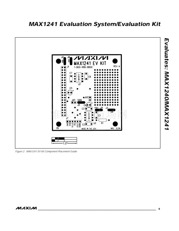
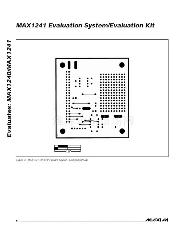
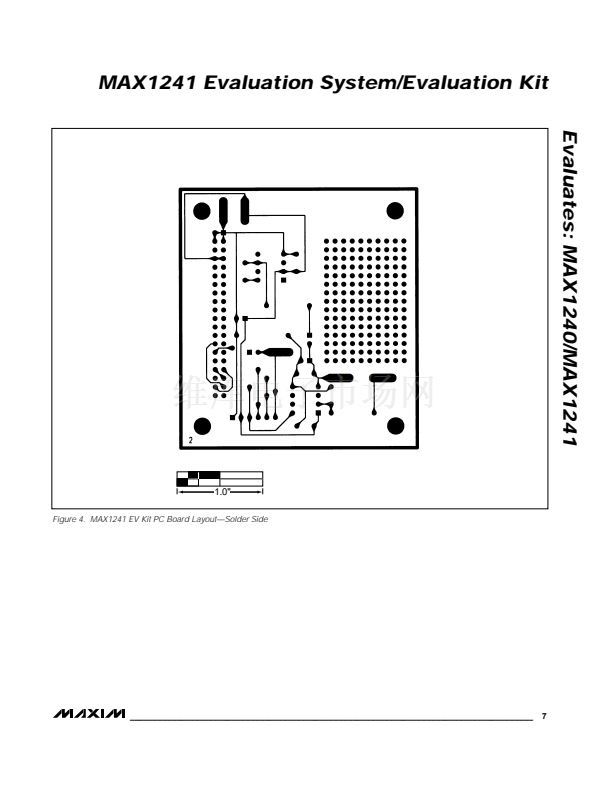
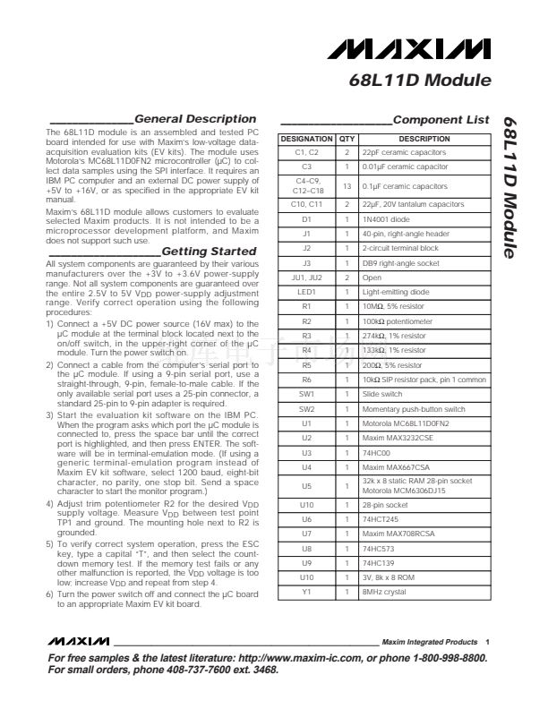
__MAX1241 EV Kit Component List
DESIGNATION
C1
C2, C3, C6
C4
C5
C7
J1
J7
JU1, JU2
R1
U1
U2
None
QTY
1
3
1
1
1
1
1
2
1
1
1
1
DESCRIPTION
0.01碌F capacitor
0.1碌F capacitors
4.7碌F capacitor
10碌F capacitor
0.047碌F capacitor
2x20 header
6-pin header
2-pin headers
1k鈩?resistor
MAX1241BCPA
MAX872CPA
PC board
MAX1241 EV System
_________________________Quick Start
The MAX1241 EV kit is fully assembled and tested.
Follow these steps to verify board operation.
Do not
turn on the power supply until all connections are
completed.
1) Copy the files from the distribution disk to your hard
disk or to blank floppy disks. The MAX1241 EV kit
software should be in its own directory. The neces-
sary files are in the distribution disk鈥檚 root directory,
and the source code is in the SOURCE subdirec-
tory. The SOURCE subdirectory is not required to
operate the EV kit.
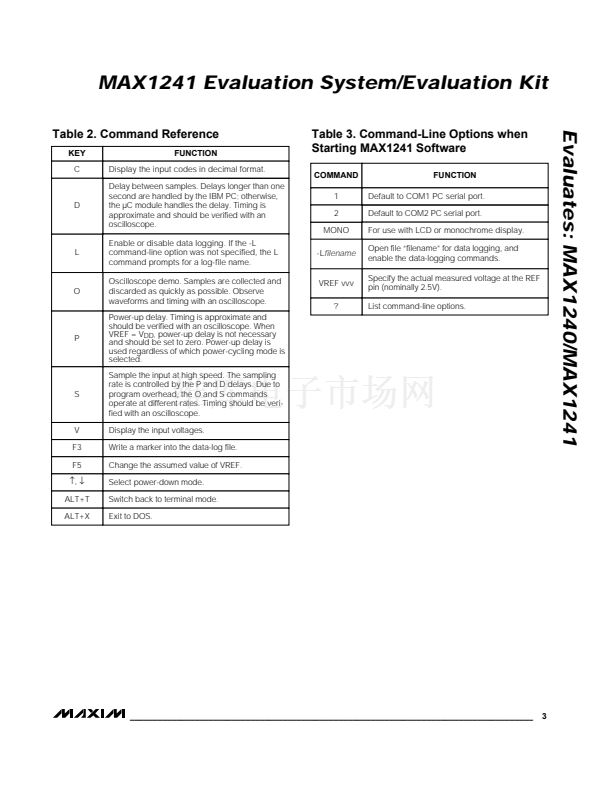
2) Make sure that jumper JU1 is open and JU2 is
closed (Table 1).
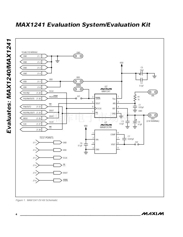
3) Carefully connect the boards by aligning the
MAX1241 EV kit鈥檚 40-pin header with the 68L11D
module鈥檚 40-pin connector. Gently press them
together. The two boards should be flush against
one another.
4) Connect a 5V DC power source (16V max) to the 碌C
module. This is located at the terminal block next to
the on/off switch, in the upper-right corner of the 碌C
module. Observe the polarity marked on the board.
__MAX1241 EVL11 Component List
QTY
1
1
DESCRIPTION
MAX1241EVKIT-DIP
68L11D
碌C
Module (68L11D MODULE)
________________________________________________________________
Maxim Integrated Products
1
For free samples & the latest literature: http://www.maxim-ic.com, or phone 1-800-998-8800.
For small orders, phone 408-737-7600 ext. 3468.


 1
1
 2
2
 3
3
 4
4
 5
5
 6
6
 7
7
 8
8
 9
9
 10
10
 11
11
 12
12
 13
13
 14
14
 15
15
 16
16
