19-2361; Rev 0; 03/02
MAX1921 Evaluation Kit
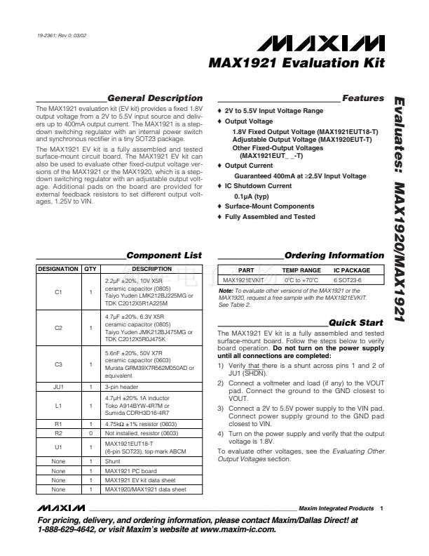
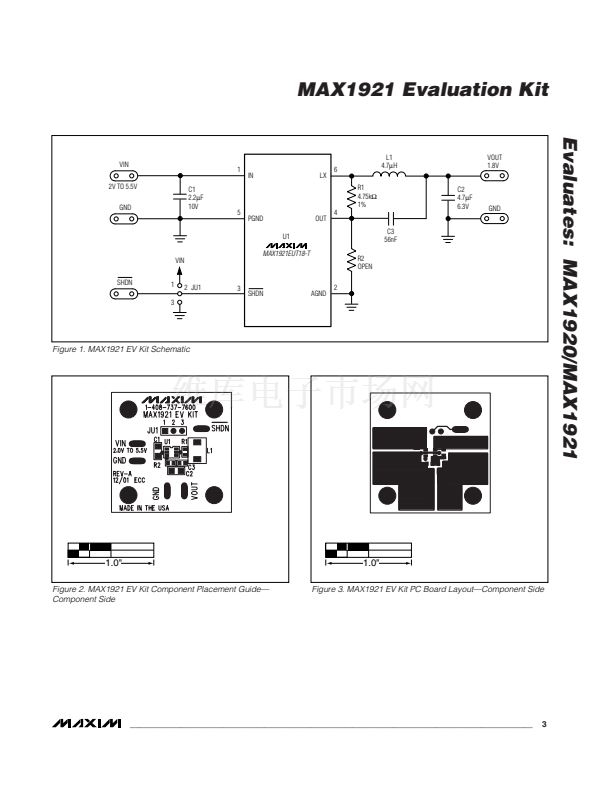
General Description
The MAX1921 evaluation kit (EV kit) provides a fixed 1.8V
output voltage from a 2V to 5.5V input source and deliv-
ers up to 400mA output current. The MAX1921 is a step-
down switching regulator with an internal power switch
and synchronous rectifier in a tiny SOT23 package.
The MAX1921 EV kit is a fully assembled and tested
surface-mount circuit board. The MAX1921 EV kit can
also be used to evaluate other fixed-output voltage ver-
sions of the MAX1921 or the MAX1920, which is a step-
down switching regulator with an adjustable output volt-
age. Additional pads on the board are provided for
external feedback resistors to set different output volt-
ages, 1.25V to VIN.
o
2V to 5.5V Input Voltage Range
o
Output Voltage
1.8V Fixed Output Voltage (MAX1921EUT18-T)
Adjustable Output Voltage (MAX1920EUT-T)
Other Fixed-Output Voltages
(MAX1921EUT_ _-T)
o
Output Current
Guaranteed 400mA at
鈮?.5V
Input Voltage
o
IC Shutdown Current
0.1碌A (typ)
o
Surface-Mount Components
o
Fully Assembled and Tested
Features
Evaluates: MAX1920/MAX1921
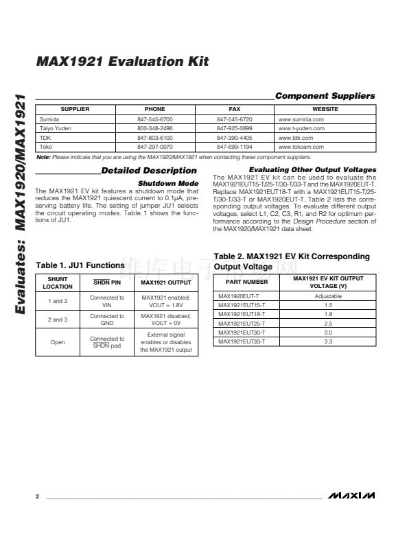
Component List
DESIGNATION
QTY
DESCRIPTION
2.2碌F 卤20%, 10V X5R
ceramic capacitor (0805)
Taiyo Yuden LMK212BJ225MG or
TDK C2012X5R1A225M
4.7碌F 卤20%, 6.3V X5R
ceramic capacitor (0805)
Taiyo Yuden JMK212BJ475MG or
TDK C2012X5R0J475K
5.6nF 卤20%, 50V X7R
ceramic capacitor (0603)
Murata GRM39X7R562M050AD or
equivalent
3-pin header
4.7碌H 卤20% 1A inductor
Toko A914BYW-4R7M or
Sumida CDRH3D16-4R7
4.75k鈩?卤1% resistor (0603)
Not installed, resistor (0603)
MAX1921EUT18-T
(6-pin SOT23), top mark ABCM
Shunt
MAX1921 PC board
MAX1921 EV kit data sheet
MAX1920/MAX1921 data sheet
PART
MAX1921EVKIT
Ordering Information
TEMP RANGE
0
o
C to +70
o
C
IC PACKAGE
6 SOT23-6
C1
1
Note:
To evaluate other versions of the MAX1921 or the
MAX1920, request a free sample with the MAX1921EVKIT.
See Table 2.
C2
1
Quick Start
The MAX1921 EV kit is a fully assembled and tested
surface-mount board. Follow the steps below to verify
board operation.
Do not turn on the power supply
until all connections are completed:
1) Verify that there is a shunt across pins 1 and 2 of
JU1 (SHDN).
2) Connect a voltmeter and load (if any) to the VOUT
pad. Connect the ground to the GND closest to
VOUT.
3) Connect a 2V to 5.5V power supply to the VIN pad.
Connect power supply ground to the GND pad
closest to VIN.
4) Turn on the power supply and verify that the output
voltage is 1.8V.
To evaluate other voltages, see the
Evaluating Other
Output Voltages
section.
C3
1
JU1
L1
R1
R2
U1
None
None
None
None
1
1
1
0
1
1
1
1
1
________________________________________________________________
Maxim Integrated Products
1
For pricing, delivery, and ordering information, please contact Maxim/Dallas Direct! at
1-888-629-4642, or visit Maxim鈥檚 website at www.maxim-ic.com.


 1
1
 2
2
 3
3
 4
4
