220掳C Max. for 10 Seconds, 1/16 in from case
鈥?/div>
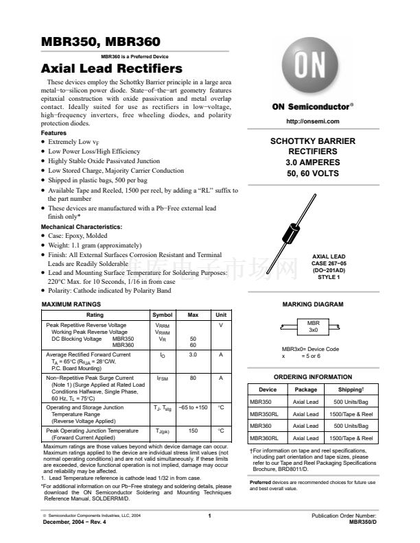
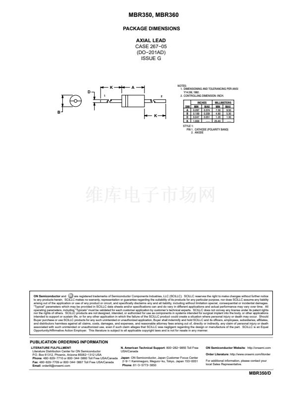
Polarity: Cathode indicated by Polarity Band
MAXIMUM RATINGS
Rating
Peak Repetitive Reverse Voltage
Working Peak Reverse Voltage
DC Blocking Voltage
MBR350
MBR360
Average Rectified Forward Current
T
A
= 65掳C (R
qJA
= 28掳C/W,
P.C. Board Mounting)
Non鈭扲epetitive Peak Surge Current
(Note 1) (Surge Applied at Rated Load
Conditions Halfwave, Single Phase,
60 Hz, T
L
= 75掳C)
Operating and Storage Junction
Temperature Range
(Reverse Voltage Applied)
Peak Operating Junction Temperature
(Forward Current Applied)
Symbol
V
RRM
V
RWM
V
R
I
O
Max
Unit
V
50
60
3.0
A
AXIAL LEAD
CASE 267鈭?5
(DO鈭?01AD)
STYLE 1
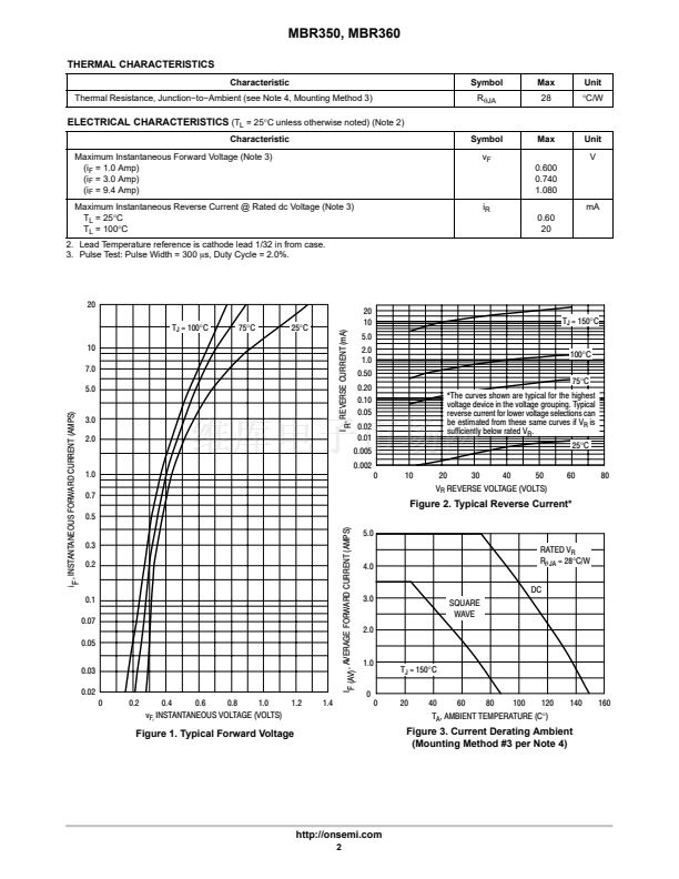
MARKING DIAGRAM
MBR
3x0
MBR3x0= Device Code
x
= 5 or 6
I
FSM
80
A
ORDERING INFORMATION
Device
Package
Axial Lead
Axial Lead
Axial Lead
Axial Lead
Shipping
鈥?/div>
500 Units/Bag
1500/Tape & Reel
500 Units/Bag
1500/Tape & Reel
T
J
, T
stg
鈭?5 to +150
掳C
MBR350
MBR350RL
T
J(pk)
150
掳C
MBR360
MBR360RL
Maximum ratings are those values beyond which device damage can occur.
Maximum ratings applied to the device are individual stress limit values (not
normal operating conditions) and are not valid simultaneously. If these limits
are exceeded, device functional operation is not implied, damage may occur
and reliability may be affected.
1. Lead Temperature reference is cathode lead 1/32 in from case.
*For additional information on our Pb鈭扚ree strategy and soldering details, please
download the ON Semiconductor Soldering and Mounting Techniques
Reference Manual, SOLDERRM/D.
漏
Semiconductor Components Industries, LLC, 2004
鈥燜or information on tape and reel specifications,
including part orientation and tape sizes, please
refer to our Tape and Reel Packaging Specifications
Brochure, BRD8011/D.
Preferred
devices are recommended choices for future use
and best overall value.
1
December, 2004 鈭?Rev. 4
Publication Order Number:
MBR350/D


 1
1
 2
2
 3
3
 4
4
