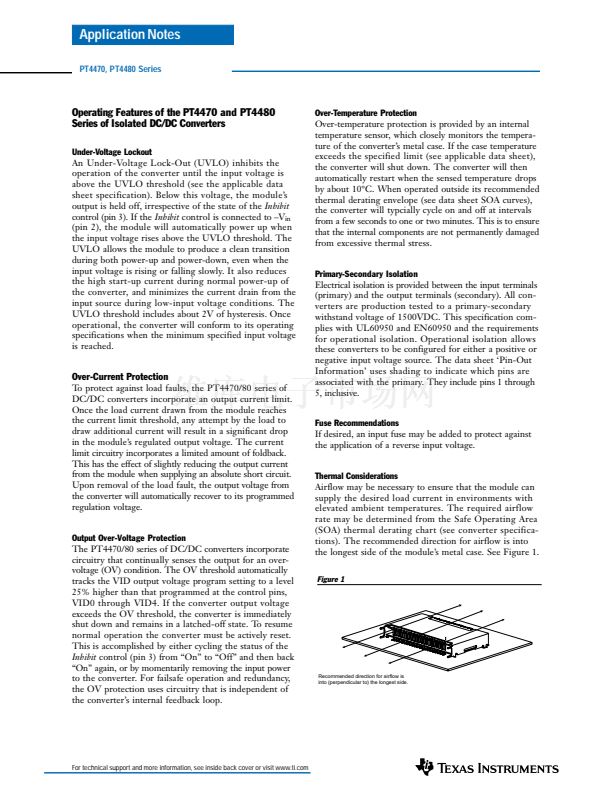
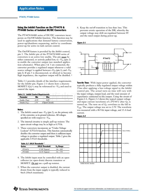
鈥?/div>
Over-Current Protection
Over-Temperature Protection
Over-Voltage Protection
Space-Saving Package
Solderable Copper Case
Safety Approvals:
UL 60950
CSA 22.2 950
VDE EN60950 Pending
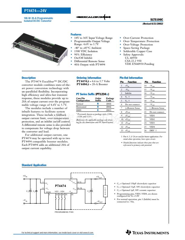
Description
The PT4474 Excalibur鈩?DC/DC
converter module combines state-of-the-
art power conversion technology with
un-paralleled flexibility. Incorporating
high efficiency and ultra-fast transient
response, these modules provide up to
20A of output current over the program-
mable voltage range of 4.6V to 5.7V.
The modules include a number of
inbuilt features to facilitate system
integration. These include a foldback
output current limit, over-temperature
protection, and an inhibit on/off control.
A differential remote sense is also provided
to compensate for voltage drop between
the converter and load.
For additional output current, one
PT4474 may be operated with up to two
PT4494 compatible booster modules.
Each PT4494 adds an additional 20A of
output current capability.
Ordering Information
PT4474o
= 4.6 to 5.7 Volts
PT4494o
= 20-A Booster
Pin-Out Information
Pin
1
2
Function
+V
in
鈥揤
in
Inhibit
V
r
鈥?/div>
V
a
鈥?/div>
Do not connect
(+)Remote Sense
+V
out
+V
out
Pin
14
15
16
17
18
19
20
21
22
23
24
25
26
Function
鈥揤
out
鈥揤
out
鈥揤
out
鈥揤
out
鈥揤
out
鈥揤
out
(鈥?Remote Sense
Do not connect
VID1
VID2
VID3
VID4
DRV 鈥?/div>
PT Series Suffix
(PT1234
x
)
Case/Pin
Configuration
Vertical
Horizontal
SMD
Order
Suffix
Package
Code *
(EKD)
(EKA)
(EKC)
3
4
5
6
7
8
9
N
A
C
* Previously known as package styles 1200,
1210, and 1215.
(Reference the applicable package code draw-
ing for the dimensions and PC board layout)
10 +V
out
11 +V
out
12 +V
out
13 +V
out
鈥?/div>
Pins 4, 5, & 26 are used for booster applications. For
stand-alone operation, leave open circuit.
鈥?Shaded functions indicate those pins that are
referenced to primary-side potential.
Standard Application
+ V
IN
1
2
C
2
+ V
in
鈥?V
in
Inhibit
3
7
+ V
sns
+ V
out
8-13
+ V
OUT
鈥?C
o
= Optional 150碌F electrolytic capacitor
+
C
o
L
O
A
D
PT4474
VID1 - VID4
22 23 24 25
-V
sns
+
C
1
-V
out
1 4 - 1 9
20
鈥?C
1
= Optional 33碌F, 50V electrolytic capacitor
鈥?C
2
= Optional 1碌F, 50V ceramic capacitor
鈥?Programming pins, VID1鈥揤ID4, are shown
configured for Vo =5.0V
鈥?For normal operation, pin 3 (Inhibit) must be
connected to 鈥揤in.
鈥?V
IN
鈥?V
OUT
PROGRAMMING PINS
For technical support and more information, see inside back cover or visit www.ti.com


 1
1
 2
2
 3
3
 4
4
 5
5
 6
6
 7
7
 8
8
