UCC29421, UCC29422, UCC39421, UCC39422
MULTIMODE HIGH FREQUENCY PWM CONTROLLER
SLUS246C 鈭?OCTOBER 1999 鈭?REVISED FEBRUARY 2005
D
Operation Down to an Input
D
D
D
D
D
D
D
D
D
D
D
D
Voltage of 1.8 V
High Efficiency Boost, SEPIC or
Flyback (Buck-Boost) Topologies
Drives External FETs for
High-Current Applications
Up to 2-MHz Oscillator
Synchronizable Fixed Frequency
Operation
High-Efficiency Low-Power Mode
High-Efficiency at Very Low-Power
with Programmable Variable
Frequency Mode
Pulse-by-Pulse Current Limit
5-碌A Supply Current in Shutdown
150-碌A Supply Current in Sleep
Mode
Selectable NMOS or PMOS
Rectification
Built-In Power-On Reset
(UCC39422 Only)
Built-In Low-Voltage Detect
(UCC39422 Only)
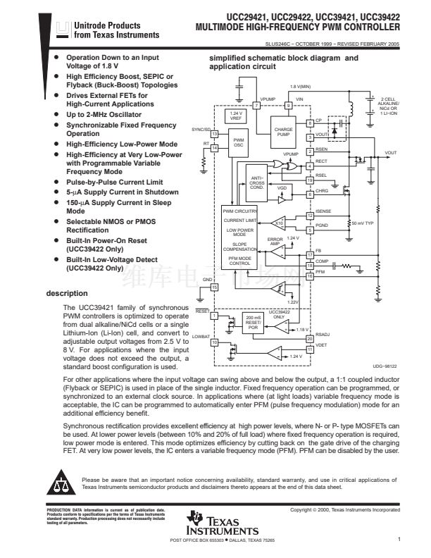
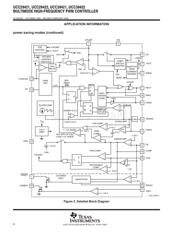
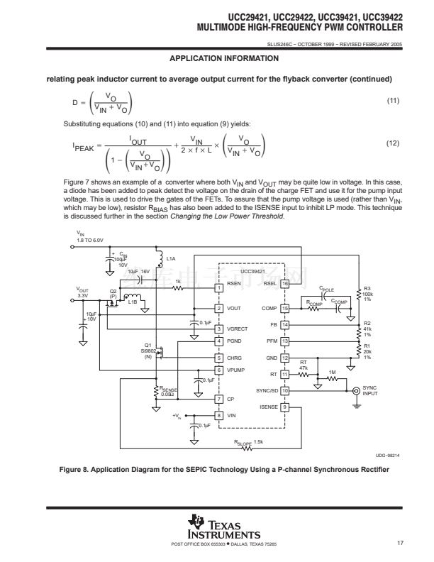
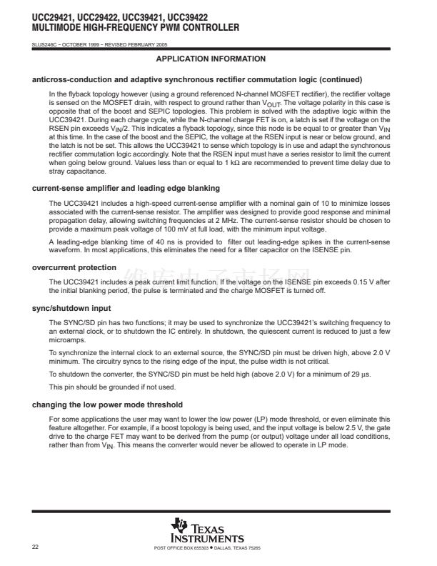
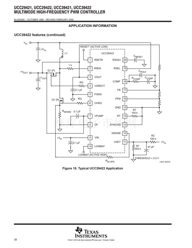
simplified schematic block diagram and
application circuit
1.8 V(MIN)
VPUMP
7
1.24 V
VREF
8
SYNC/SD
13
RT
14
PWM
OSC
VPUMP
CHARGE
PUMP
3
2
4
ANTI鈭?/div>
CROSS
COND.
RSEL
19
VGD
6
CHRG
9
VIN
+
2 CELL
ALKALINE/
NiCd OR
+
1 LI鈭扞ON
CP
VOUT
RSEN
RECT
VOUT
PWM CIRCUITRY
CURRENT LIMIT
LOW POWER
MODE
SLOPE
COMPENSATION
PFM MODE
CONTROL
+
X10
12
ISENSE
PGND
5
ERROR 1.24 V
AMP
+
17
COMP
18
PFM
16
50 mV TYP
FB
GND
15
description
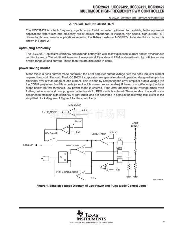
The UCC39421 family of synchronous
PWM controllers is optimized to operate
from dual alkaline/NiCd cells or a single
Lithium-Ion (Li-Ion) cell, and convert to
adjustable output voltages from 2.5 V to
8 V. For applications where the input
voltage does not exceed the output, a
standard boost configuration is used.
RESET
1
200 mS
RESET/
POR
+
1.22V
UCC39422
ONLY
+
1.18 V
RSADJ
10
+
1.24 V
UDG鈭?8122
20
VDET
11
LOWBAT
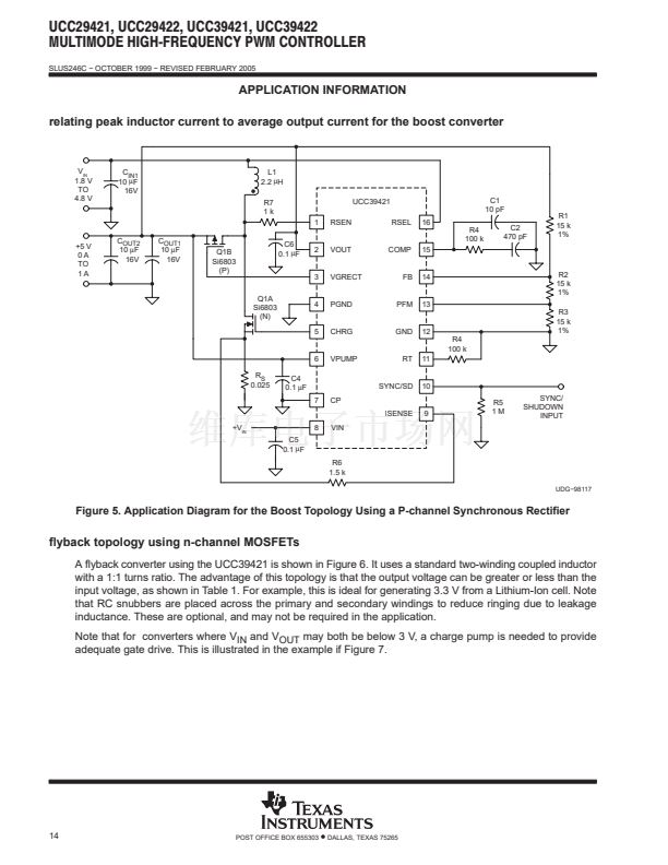
For other applications where the input voltage can swing above and below the output, a 1:1 coupled inductor
(Flyback or SEPIC) is used in place of the single inductor. Fixed frequency operation can be programmed, or
synchronized to an external clock source. In applications where (at light loads) variable frequency mode is
acceptable, the IC can be programmed to automatically enter PFM (pulse frequency modulation) mode for an
additional efficiency benefit.
Synchronous rectification provides excellent efficiency at high power levels, where N- or P- type MOSFETs can
be used. At lower power levels (between 10% and 20% of full load) where fixed frequency operation is required,
low power mode is entered. This mode optimizes efficiency by cutting back on the gate drive of the charging
FET. At very low power levels, the IC enters a variable frequency mode (PFM). PFM can be disabled by the user.
Please be aware that an important notice concerning availability, standard warranty, and use in critical applications of
Texas Instruments semiconductor products and disclaimers thereto appears at the end of this data sheet.
PRODUCTION DATA information is current as of publication date.
Products conform to specifications per the terms of Texas Instruments
standard warranty. Production processing does not necessarily include
testing of all parameters.
Copyright
铮?/div>
2000, Texas Instruments Incorporated
POST OFFICE BOX 655303
鈥?/div>
DALLAS, TEXAS 75265
1


 1
1
 2
2
 3
3
 4
4
 5
5
 6
6
 7
7
 8
8
 9
9
 10
10
 11
11
 12
12
 13
13
 14
14
 15
15
 16
16
 17
17
 18
18
 19
19
 20
20
 21
21
 22
22
 23
23
 24
24
 25
25
 26
26
 27
27
 28
28
 29
29
 30
30
 31
31
 32
32
 33
33
 34
34
 35
35
