鈥?/div>
Very Low Phase Jitter
4.50
unloaded
30
10 LSTTL
@ 50%Vcc
40
Tr/Tf 20 % to 80%
8
Voh Loaded, over all .9Vcc
Vol Loaded, over all
Ts
1蟽
2
3
2
Environmental and Mechanical
Operating temp.
range
Mechanical Shock
Thermal Shock
Vibration
Soldering
Conditions
Hermetic Seal
Pin Out
0掳C to 70掳C (-40掳C to 85掳C available)
Per MIL-STD-202, Method 213, Cond. E
Per MIL-STD-883, Method 1011, Cond. A
Per MIL-STD-883, Method 2007, Cond. A
260掳C, for 10s, Max.
Leak rate less than 5x10⁻⁸ atm.ccm/s of helium
Pin #1 - Tri-State Control
Pin #3 - Output
Pin #2 - Case, GND
Pin #4 - Vcc
Electrical Connections:
Notes:
1.
Standard frequency stability, others available.
2.
Typical current load and frequency dependent.
3.
Standard symmetry, tighter available.
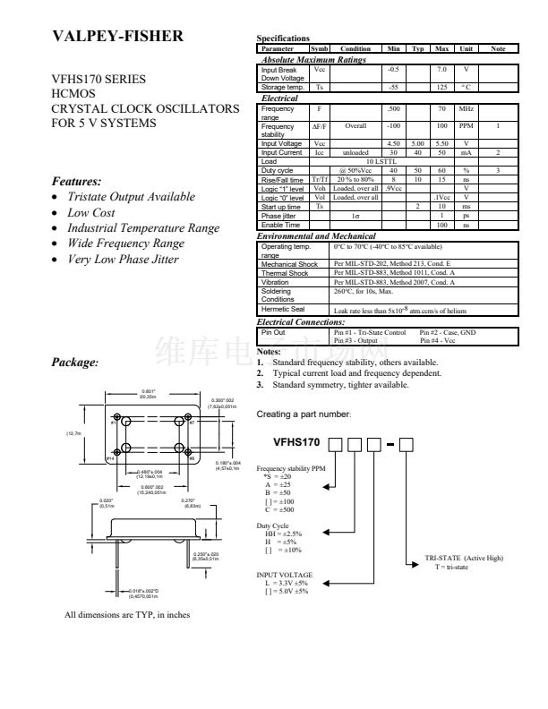
0.801"
(
20,35m
Package
:
0.300".002
(7,62卤0,051m
Creating a part number
:
#1
(12,7m
#7
VFHS170
#14
0.480"卤.004
(12,19卤0,1m
0.600".002
(15,240,051m
0.020"
(0,51m
0.270"
(6,83m)
#8
0.180"卤.004
(4,57卤0,1m
Frequency stability PPM
*S = 卤20
A = 卤25
B = 卤50
[ ] = 卤100
C = 卤500
Duty Cycle
HH = 卤2.5%
H = 卤5%
[ ] = 卤10%
TRI-STATE (Active High)
T = tri-state
INPUT VOLTAGE
L = 3.3V 卤5%
[ ] = 5.0V 卤5%
0.250"卤.020
(6,35卤0,51m
0.018"卤.002"D
(0,4570,051m
All dimensions are TYP, in inches


 1
1
