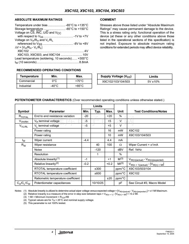
鈥?X9C104 = 100k鈩?/div>
鈥?Packages
鈥?-lead SOIC and DIP
鈥?Pb-free plus anneal available (RoHS compliant)
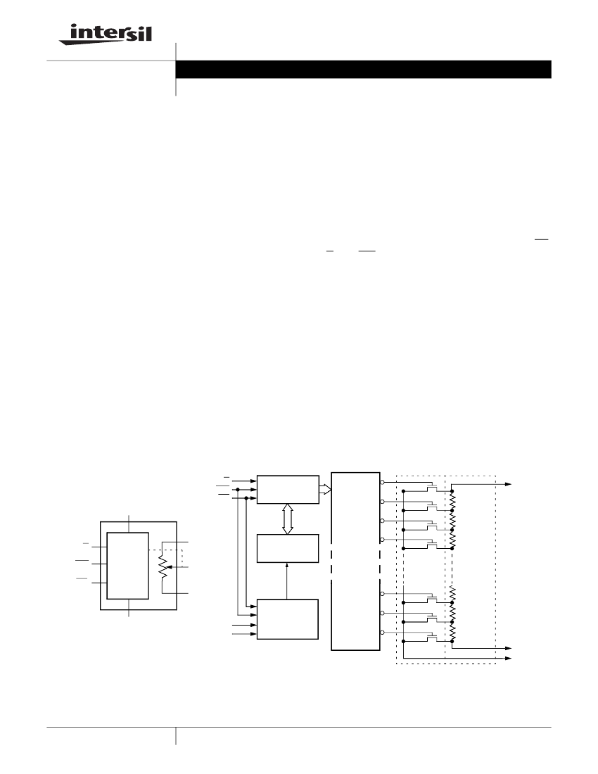
BLOCK DIAGRAM
U/D
INC
CS
V
CC
(Supply Voltage)
7-Bit
Up/Down
Counter
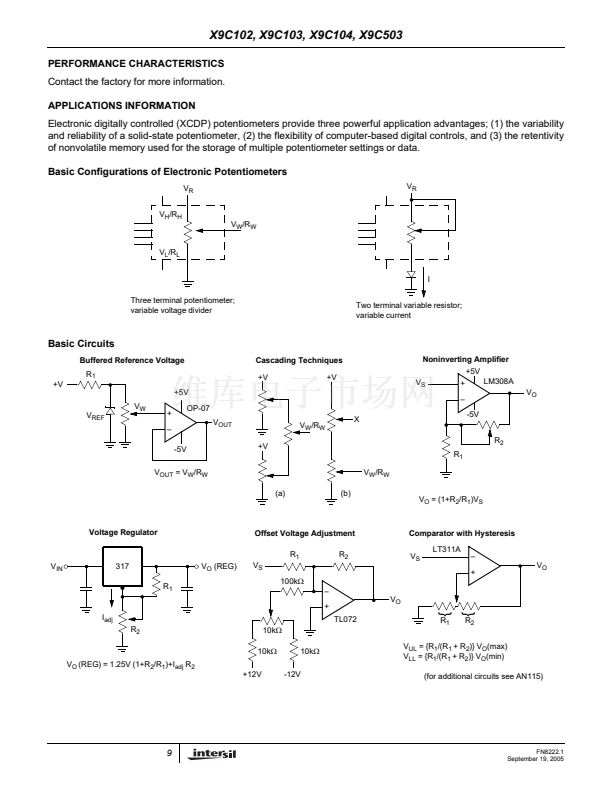
DESCRIPTION
The X9Cxxx are Intersil digitally controlled (XDCP)
potentiometers. The device consists of a resistor
array, wiper switches, a control section, and nonvola-
tile memory. The wiper position is controlled by a
three-wire interface.
The potentiometer is implemented by a resistor array
composed of 99 resistive elements and a wiper switch-
ing network. Between each element and at either end
are tap points accessible to the wiper terminal. The
position of the wiper element is controlled by the CS,
U/D, and INC inputs. The position of the wiper can be
stored in nonvolatile memory and then be recalled
upon a subsequent power-up operation.
The device can be used as a three-terminal potentiom-
eter or as a two-terminal variable resistor in a wide
variety of applications including:
鈥?control
鈥?parameter adjustments
鈥?signal processing
99
98
97
R
H
/V
H
Up/Down
(U/D)
Increment
(INC)
Device
Select (CS)
V
H
/R
H
Control
and
Memory
R
W
/V
W
V
L
/R
L
7-Bit
Nonvolatile
Memory
96
One
of
One-
Hundred
Decoder
2
Transfer
Gates
Resistor
Array
V
SS
(Ground)
General
V
CC
GND
Store and
Recall
Control
Circuitry
1
0
R
L
/V
L
R
W
/V
W
Detailed
1
CAUTION: These devices are sensitive to electrostatic discharge; follow proper IC Handling Procedures.
1-888-INTERSIL or 1-888-468-3774
|
Intersil (and design) is a registered trademark of Intersil Americas Inc.
XDCP is a trademark of Intersil Americas Inc. Copyright Intersil Americas Inc. 2005. All Rights Reserved
All other trademarks mentioned are the property of their respective owners.


 1
1
 2
2
 3
3
 4
4
 5
5
 6
6
 7
7
 8
8
 9
9
 10
10
 11
11
