IDT77301
UtopiaFIFO鈩?1 to 4 (128 x 9 x 4) Demultiplexer-FIFO
Commercial and Industrial Temperature Ranges
and is available.) A new FIFO location can only be selected after current
cell transfer is complete.
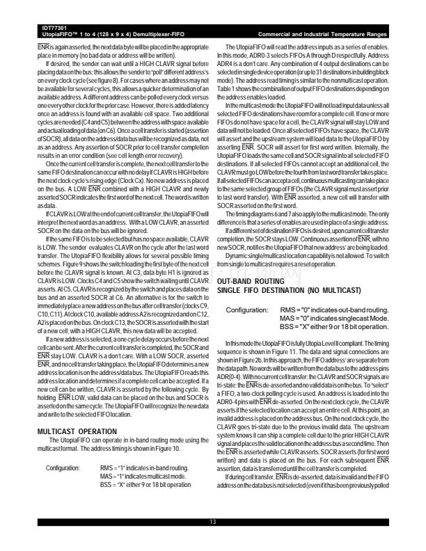
During cell transfer, FIFO 鈥減olling鈥?can take place. At any time when
the
ENR
is asserted, if a valid address is placed on the address bus, the
CLAVR signal will notify the upstream system if the polled address can take
a cell. As delineated in the Utopia Level II specifications, a valid address
may only be placed on the bus every other cycle. After the invalid address
cycle, the CLAVR will always go tri-state. This polling will not affect current
cell transfer or the FIFO selected for the next cell transfer.
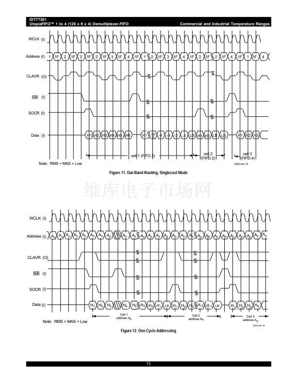
Figure 11 shows polling can take place while the current FIFO is
transferring data; the current FIFO can remain as the 鈥渟elected鈥?FIFO for
a continuous cell transfer. If the next (different) FIFO destination has been
polled and has space available, cell transfer will have a one cycle delay.
To select a new location, the
ENR
must de-assert while the new address
is on the address bus. After the last word of the first cell transfer, the SOCR
tri-states and
ENR
de-asserts. At this time the new address (previously
polled and determined to have space available) is placed on the address
bus. At this time the CLAVR is tri-state from the previous invalid address.
On the following cycle, CLAVR,
ENR,
and SOCR all assert and data is
written into the FIFO. An invalid address is then placed on the address bus.
On subsequent clocks with
ENR
asserted, data is placed on the bus until
cell transfer is complete. If the next FIFO destination is the same as the prior
address, and is known to have a cell available from prior polling, continuous
cell transfer can take place.
While the previous operation, as shown in Figure 11, conforms to Utopia
Level II specifications, the UtopiaFIFO is capable of faster data transfer
which is not Utopia II compliant but, nonetheless, may be desired. Figure
12 shows a 鈥渙ne-cycle鈥?addressing scheme where a null address (1F)
need not be placed between valid addresses. In this implementa-
tion the latency from address with an available cell space to data
transfer is reduced from three to two cycles. While polling new FIFO
destinations, a new address can be polled every cycle; this doubles how
quickly the switch can determine the next destination availability and
reduces potential 鈥渨ait states鈥?
mode described above, the next Multicast FIFO Combination Enables can
be placed on the address bus. Upon receiving a HIGH CLAVR,
ENR
asserts, data is written into the FIFO and SOCR is set HIGH for the first word
written. Subsequent
ENR
assertions will load the remaining words of the
cell into the FIFO鈥檚. If CLAVR is HIGH prior to the last word written, and
the next set of cell destinations is the same, continuous cell transfer can
occur. The
ENR
stays LOW and the SOCR asserts for the first word of
the next cell. The new SOCR signal indicates data is on the bus.
After the cell is transferred, if a new set of FIFO destinations is to be
selected, the SOCR tri-states while
ENR
is de-asserted. A combination
of a tri-stated SOCR and HIGH
ENR
indicates a new set of enables is on
the address bus. Due to prior polling of this combination, the switch knows
the set of FIFO destinations are available. If no prior polling, the switch will
need to go through the 鈥渢wo-cycle鈥?polling scheme described earlier (until
all destinations can accept a complete cell). On the next clock cycle, SOCR
goes HIGH to indicate the start of a new cell (clock Cx).
ENR
is asserted
and data placed on the data bus. Changing the set of FIFO destinations
during multicast results in only a one clock cycle delay if the new locations
are available.
Building Block Implementation
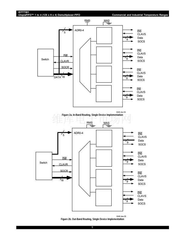
IN-BAND ROUTING
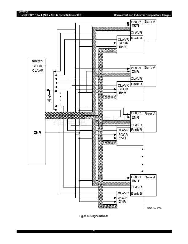
SINGLE FIFO DESTINATION (NO MULTICAST)
Configuration:
RMS = 鈥?鈥?indicates in-band routing.
MAS = 鈥?鈥?indicates singlecast mode.
BSS = 鈥?鈥?18 bit operation
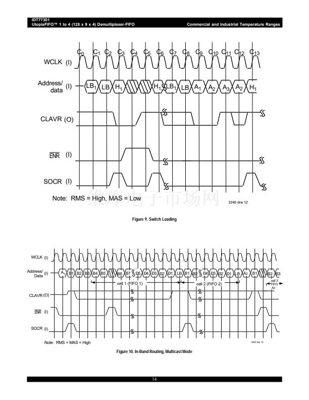
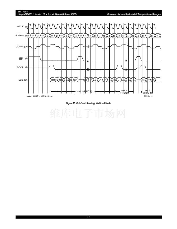
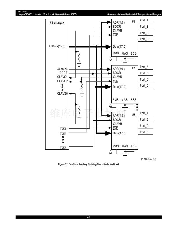
MULTICAST OPERATION
Configuration:
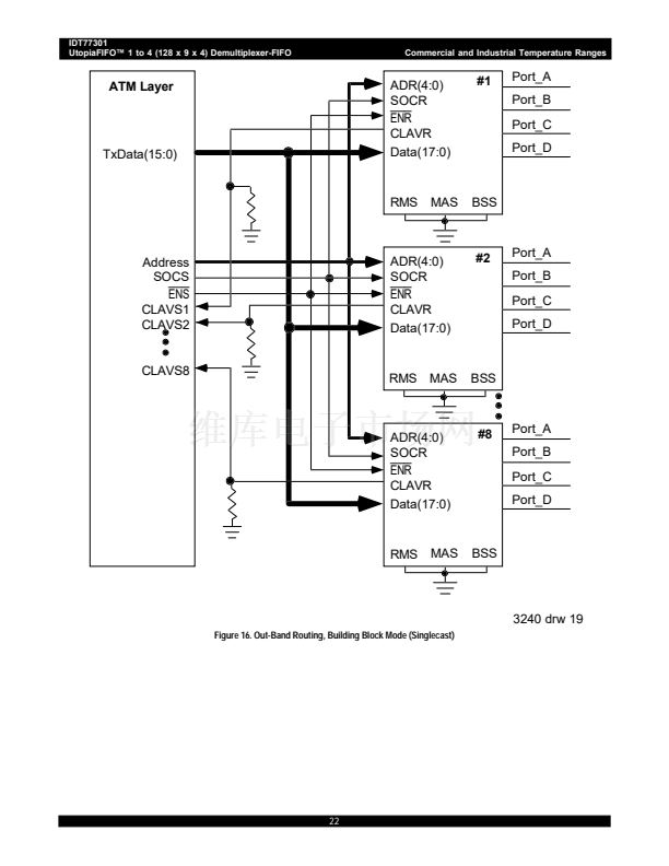
RMS = 鈥?鈥?indicates out-band routing.
MAS = 鈥?鈥?indicates multicast mode.
BSS = 鈥淴鈥?either 9 or 18-bit operation
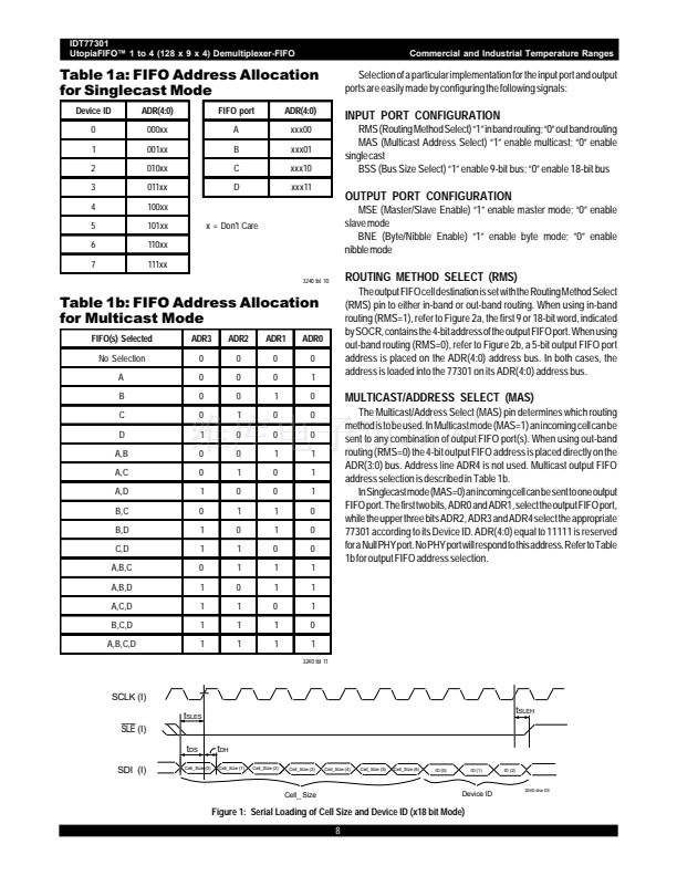
In this mode the address lines are read by the UtopiaFIFO as a series
of Enable signals (no longer Utopia Specification Level II compliant). The
input timing is shown in Figure 13. The least four significant bits (A0-A3)
are read (A4 is DC). These four inputs will allow any combination of the
four output FIFOs to receive the next cell. Table 1 delineates the output
FIFO combination for each Enable signal A0-A3 combination. The device
will only accept data when all selected FIFOs have a cell available. If one
or more FIFOs do not have a complete cell size available, the CLAVR signal
will remain LOW.
FIFO 鈥減olling鈥?can occur in this mode. As with the single destination
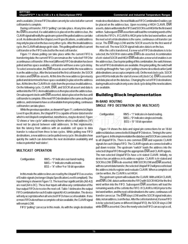
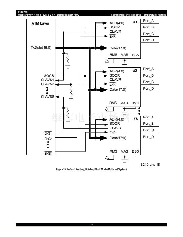
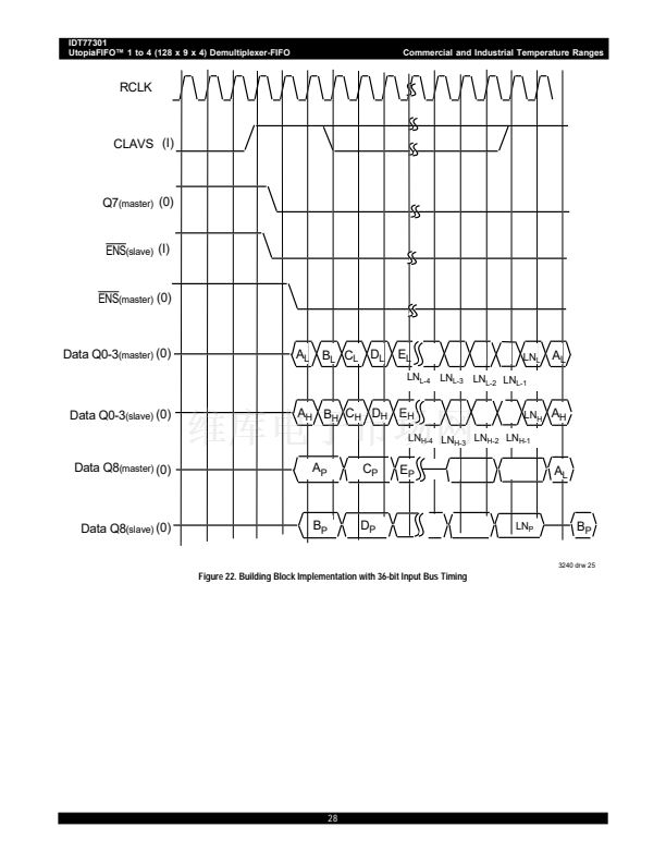
Figure 14 shows the data and signal pin connections for an 18-bit
address/data bus connected to 8 UtopiaFIFO devices. Timing is the same
as in Figure 6. In this implementation the data bus and SOCR are connected
to all UtopiaFIFOs. There is one common
ENR
and separate CLAVR
signals for each Utopia FIFO. The CLAVR signals are connected with a
pull down resistor. The upstream 鈥渟witch鈥?loads the address into the
selected UtopiaFIFO through the appropriate
ENR
and CLAVR signals.
The non-selected UtopiaFIFOs have a tri-stated CLAVR. Initially, no
device has an address in its address register. CLAVR is tri-stated and
SOCR is LOW.
ENR
is de-asserted. With SOCR LOW and
ENR
asserted,
with no current data transfer, the selected UtopiaFIFO will proceed to load
the address into its register and evaluate CLAVR. When a complete cell
can be written, the CLAVR is set HIGH.
The upstream system will evaluate the CLAVR. With a HIGH CLAVR,
and
ENR
LOW, data is written into the FIFO with SOCR HIGH for the first
word written into the FIFO. Subsequent
ENR
assertions will load the
remaining words of the cell into the FIFO. If CLAVR is HIGH prior to the
last word written, and the next cell destination is the same, continuous cell
transfer can occur. The
ENR
stays LOW and the SOCR signal indicates
data, not an address, is on the bus. After the cell is transferred, if a new FIFO
is to be selected (same or different UtopiaFIFO), the SOCR stays LOW
while
ENR
is asserted. Once the newly selected FIFO can accept a cell,
16


 1
1
 2
2
 3
3
 4
4
 5
5
 6
6
 7
7
 8
8
 9
9
 10
10
 11
11
 12
12
 13
13
 14
14
 15
15
 16
16
 17
17
 18
18
 19
19
 20
20
 21
21
 22
22
 23
23
 24
24
 25
25
 26
26
 27
27
 28
28
 29
29
