PIC16F818/819
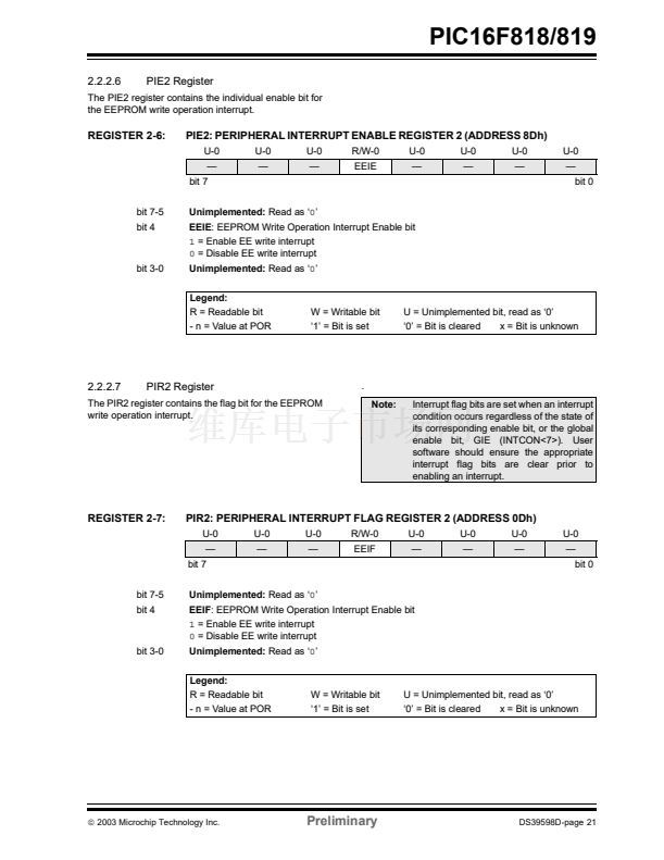
7.0
TIMER1 MODULE
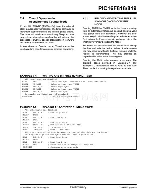
The operating mode is determined by the clock select
bit, TMR1CS (T1CON<1>).
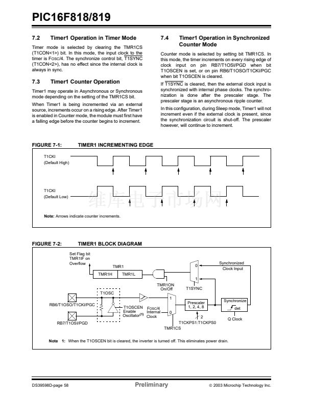
In Timer mode, Timer1 increments every instruction
cycle. In Counter mode, it increments on every rising
edge of the external clock input.
Timer1 can be enabled/disabled by setting/clearing
control bit, TMR1ON (T1CON<0>).
Timer1 also has an internal 鈥淩eset input鈥? This Reset
can be generated by the CCP1 module as the special
event trigger (see
Section 9.1 鈥淐apture Mode鈥?.
Register 7-1 shows the Timer1 Control register.
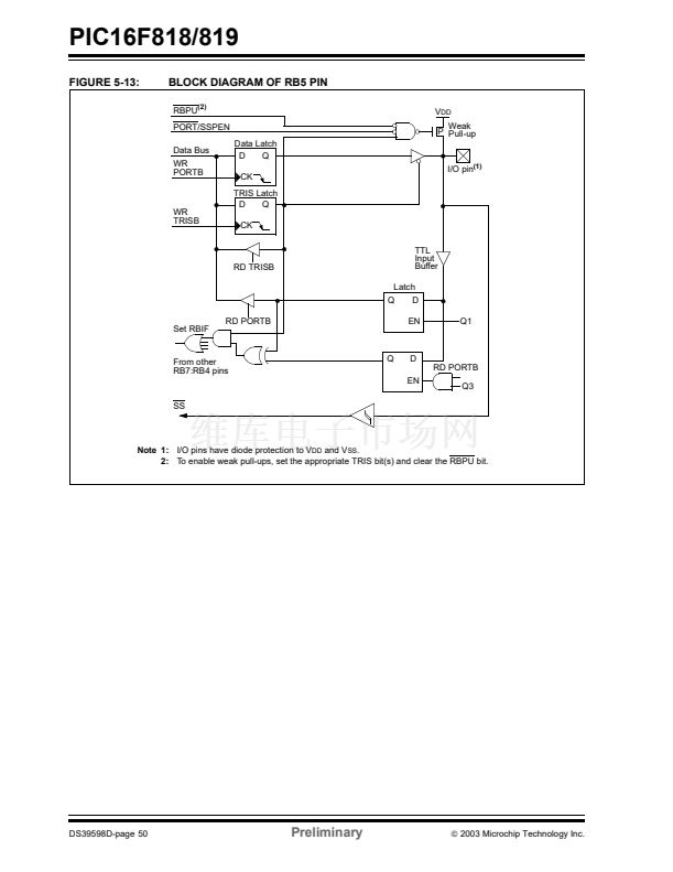
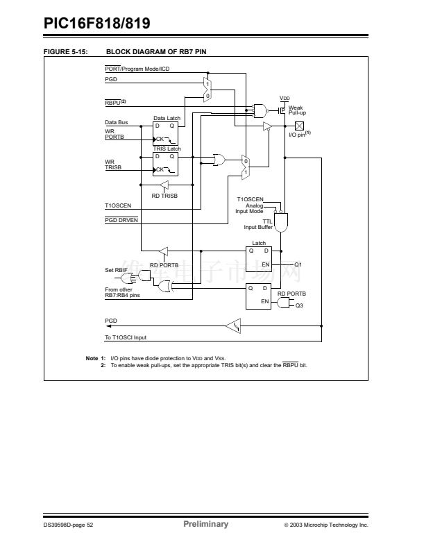
When the Timer1 oscillator is enabled (T1OSCEN is
set), the RB6/T1OSO/T1CKI/PGC and RB7/T1OSI/
PGD pins become inputs. That is, the TRISB<7:6>
value is ignored and these pins read as 鈥?鈥?
Additional information on timer modules is available in
the PICmicro
庐
Mid-Range MCU Family Reference
Manual (DS33023).
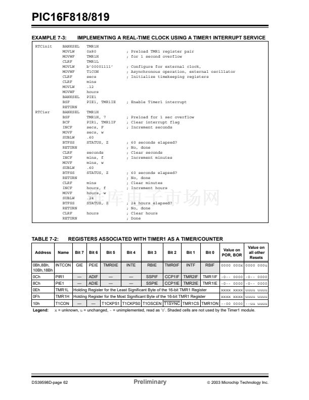
The Timer1 module is a 16-bit timer/counter consisting
of two 8-bit registers (TMR1H and TMR1L) which are
readable and writable. The TMR1 register pair
(TMR1H:TMR1L) increments from 0000h to FFFFh
and rolls over to 0000h. The TMR1 interrupt, if enabled,
is generated on overflow which is latched in interrupt
flag bit, TMR1IF (PIR1<0>). This interrupt can be
enabled/disabled by setting/clearing TMR1 Interrupt
Enable bit, TMR1IE (PIE1<0>).
Timer1 can also be used to provide real-time clock
(RTC) functionality to applications with only a minimal
addition of external components and code overhead.
7.1
Timer1 Operation
Timer1 can operate in one of three modes:
鈥?as a timer
鈥?as a synchronous counter
鈥?as an asynchronous counter
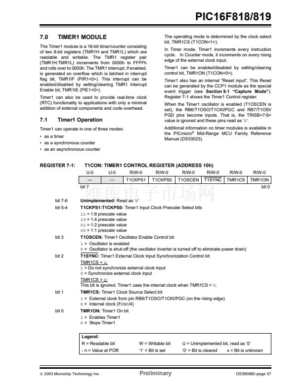
REGISTER 7-1:
T1CON: TIMER1 CONTROL REGISTER (ADDRESS 10h)
U-0
鈥?/div>
bit 7
U-0
鈥?/div>
R/W-0
T1CKPS1
R/W-0
T1CKPS0
R/W-0
T1OSCEN
R/W-0
T1SYNC
R/W-0
TMR1CS
R/W-0
TMR1ON
bit 0
bit 7-6
bit 5-4
Unimplemented:
Read as 鈥?鈥?/div>
T1CKPS1:T1CKPS0:
Timer1 Input Clock Prescale Select bits
11
= 1:8 prescale value
10
= 1:4 prescale value
01
= 1:2 prescale value
00
= 1:1 prescale value
T1OSCEN:
Timer1 Oscillator Enable Control bit
1
= Oscillator is enabled
0
= Oscillator is shut-off (the oscillator inverter is turned off to eliminate power drain)
T1SYNC:
Timer1 External Clock Input Synchronization Control bit
TMR1CS =
1:
1
= Do not synchronize external clock input
0
= Synchronize external clock input
TMR1CS =
0:
This bit is ignored. Timer1 uses the internal clock when TMR1CS =
0.
TMR1CS:
Timer1 Clock Source Select bit
1
= External clock from pin RB6/T1OSO/T1CKI/PGC (on the rising edge)
0
= Internal clock (F
OSC
/4)
TMR1ON:
Timer1 On bit
1
= Enables Timer1
0
= Stops Timer1
Legend:
R = Readable bit
- n = Value at POR
W = Writable bit
鈥?鈥?= Bit is set
U = Unimplemented bit, read as 鈥?鈥?/div>
鈥?鈥?= Bit is cleared
x = Bit is unknown
bit 3
bit 2
bit 1
bit 0
铮?/div>
2003 Microchip Technology Inc.
Preliminary
DS39598D-page 57
PIC16F819 PDF文件相关型号
PIC16F83,PIC16F84,PIC16F85,PIC16F86
PIC16F819相关型号PDF文件下载
-
型号
版本
描述
厂商
下载
-
英文版
8-Pin FLASH-Based 8-Bit CMOS Microcontrollers
-
英文版
8-Pin, 8-Bit CMOS Microcontroller with EEPROM Data Memory
MICROCHIP ...
-
英文版
8-Pin, 8-Bit CMOS Microcontroller with A/D Converter and EEP...
MICROCHIP ...
-
英文版
8-Pin, 8-Bit CMOS Microcontrollers
MICROCHIP ...
-
英文版
EPROM Memory Programming Specification
MICROCHIP ...
-
英文版
8-Pin FLASH-Based 8-Bit CMOS Microcontrollers
MICROCHIP ...
-
英文版
Microcontroller
-
英文版
Microcontroller
-
英文版
Microcontroller
ETC
-
英文版
EPROM-Based 8-Bit CMOS Microcontroller
-
英文版
8-Pin, 8-Bit CMOS Microcontrollers
-
英文版
8-Pin, 8-Bit CMOS Microcontrollers
MICROCHIP ...
-
英文版
ETC
-
英文版
EPROM Memory Programming Specification
-
英文版
EPROM Memory Programming Specification
MICROCHIP ...
-
英文版
28-Pin Programmable Mixed Signal Controller
-
英文版
EPROM Memory Programming Specification
-
英文版
Microcontroller
ETC
-
英文版
Microcontroller
ETC
-
英文版
EPROM/ROM-Based 8-Bit CMOS Microcontroller Series


 1
1
 2
2
 3
3
 4
4
 5
5
 6
6
 7
7
 8
8
 9
9
 10
10
 11
11
 12
12
 13
13
 14
14
 15
15
 16
16
 17
17
 18
18
 19
19
 20
20
 21
21
 22
22
 23
23
 24
24
 25
25
 26
26
 27
27
 28
28
 29
29
 30
30
 31
31
 32
32
 33
33
 34
34
 35
35
 36
36
 37
37
 38
38
 39
39
 40
40
 41
41
 42
42
 43
43
 44
44
 45
45
 46
46
 47
47
 48
48
 49
49
 50
50
 51
51
 52
52
 53
53
 54
54
 55
55
 56
56
 57
57
 58
58
 59
59
 60
60
 61
61
 62
62
 63
63
 64
64
 65
65
 66
66
 67
67
 68
68
 69
69
 70
70
 71
71
 72
72
 73
73
 74
74
 75
75
 76
76
 77
77
 78
78
 79
79
 80
80
 81
81
 82
82
 83
83
 84
84
 85
85
 86
86
 87
87
 88
88
 89
89
 90
90
 91
91
 92
92
 93
93
 94
94
 95
95
 96
96
 97
97
 98
98
 99
99
 100
100
 101
101
 102
102
 103
103
 104
104
 105
105
 106
106
 107
107
 108
108
 109
109
 110
110
 111
111
 112
112
 113
113
 114
114
 115
115
 116
116
 117
117
 118
118
 119
119
 120
120
 121
121
 122
122
 123
123
 124
124
 125
125
 126
126
 127
127
 128
128
 129
129
 130
130
 131
131
 132
132
 133
133
 134
134
 135
135
 136
136
 137
137
 138
138
 139
139
 140
140
 141
141
 142
142
 143
143
 144
144
 145
145
 146
146
 147
147
 148
148
 149
149
 150
150
 151
151
 152
152
 153
153
 154
154
 155
155
 156
156
 157
157
 158
158
 159
159
 160
160
 161
161
 162
162
 163
163
 164
164
