ISL5416
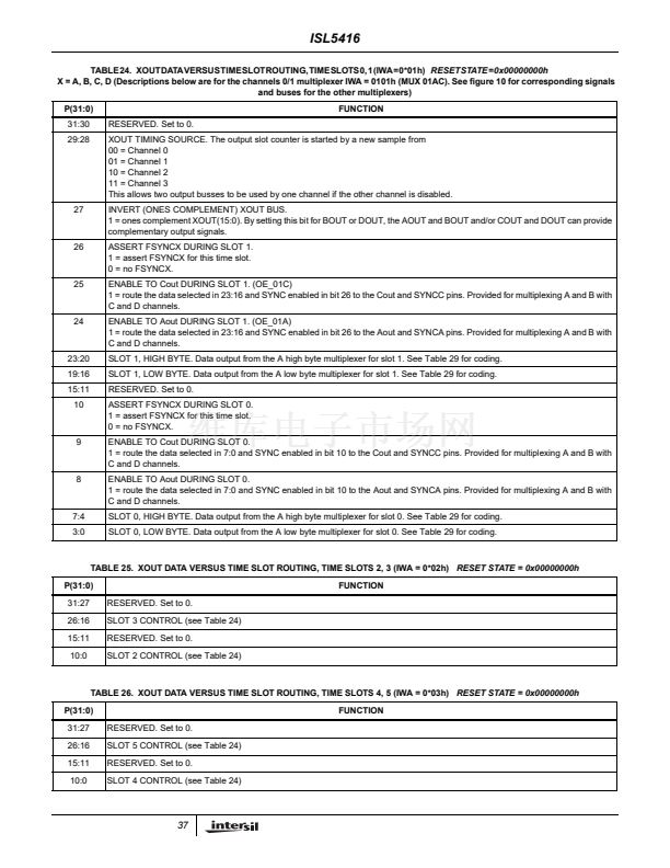
TABLE 27. XOUT DATA VERSUS TIME SLOT ROUTING, TIME SLOTS 6, 7 (IWA = 0*04h)
RESET STATE = 0x00000000h
P(31:0)
31:27
26:16
15:11
10:0
RESERVED.
SLOT 7 CONTROL (see Table 24)
RESERVED.
SLOT 6 CONTROL (see Table 24)
FUNCTION
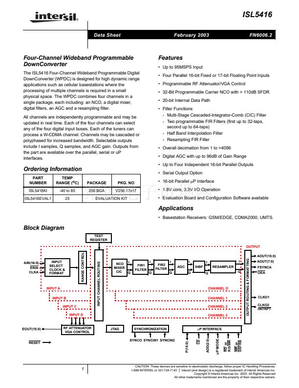
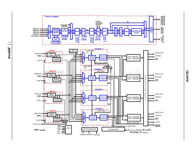
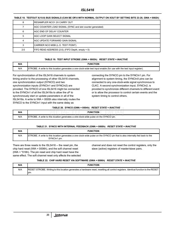
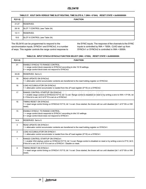
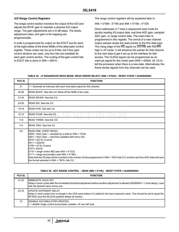
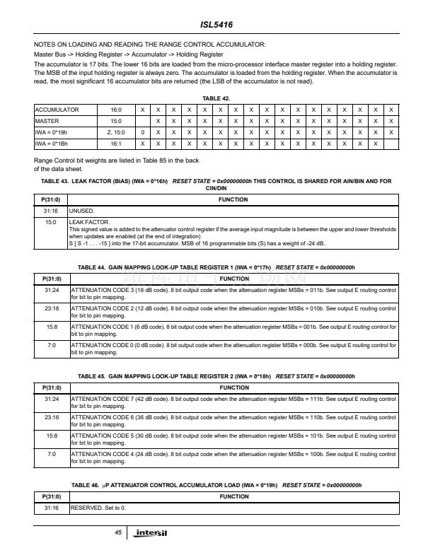
The ISL5416 can be programmed to respond to the
synchronization inputs, SYNCIn1 and SYNCIn2, in a number
of ways. This register controls the range control response to
the SYNC inputs. The response of the channels to the SYNC
inputs is controlled by IWA = *000h. CLKO start up from
SYNCIn1 or SYNCIn2 is controlled in IWA = 0000h.
TABLE 28. INPUT SYNCIn1/SYNCIn2 FUNCTION SELECT (IWA = 0*05h)
RESET STATE = 0x00000000h
P(31:0)
31
FUNCTION
ENABLE SYNCIn2 TO RANGE CONTROL.
1 = range control block responds to SYNCIn2 according to bits 19:16 settings.
0 = range control block does not respond to SYNCIn2.
RESERVED. Set to 0.
READ UPDATE ON SYNCIn2.
1 = attenuator control accumulator contents are transferred to the read holding register on SYNCIn2.
LOAD ACCUMULATOR ON SYNCIn2.
1 = attenuator control accumulator is loaded from the uP load register (0*19) on a SYNCIn2.
RANGE CONTROL STARTUP ON SYNCIn2.
1 = enable range control on SYNCIn2 if 0*10, bit 1 is set. Range control is disabled on reset or by writing a zero to IWA = 0*10h, bit
0. If this bit is set, bit 0 of 0*10 is set on a SYNCIn2.
TIMING RESET ON SYNCIn2.
1 = reset range control timing on SYNCIn2 if 0*10, bit 1 is set. Once started, the timers will run until disabled (bit 1 of 0*10h or HW
reset).
ENABLE SYNCIn1 TO RANGE CONTROL.
1 = range control block responds to SYNCIn1 according to bits 3:0 settings.
0 = range control block does not respond to SYNCIn1.
RESERVED. Set to 0.
READ UPDATE ON SYNCIn1.
1 = attenuator control accumulator contents are transferred to the read holding register on SYNCIn1.
LOAD ACCUMULATOR ON SYNCIn1.
1 = attenuator control accumulator is loaded from the uP load register (0*19) on a SYNCIn1.
RANGE CONTROL STARTUP ON SYNCIn1.
1 = enable VGA startup control on SYNCIn2 if 0*10, bit 1 is set. Range control is disabled on reset or by writing a zero to 0*10, bit 0.
If this bit is set, bit 0 of 0*10 is set on a SYNCIn1. Disable on reset.
TIMING RESET ON SYNCIn1.
1 = reset range control timing on SYNCIn1 if 0*10, bit 1 is set. Once started, the timers will run until disabled (bit 1 of 0*10h or HW
reset).
30:20
19
18
17
16
15
14:4
3
2
1
0
38


 1
1
 2
2
 3
3
 4
4
 5
5
 6
6
 7
7
 8
8
 9
9
 10
10
 11
11
 12
12
 13
13
 14
14
 15
15
 16
16
 17
17
 18
18
 19
19
 20
20
 21
21
 22
22
 23
23
 24
24
 25
25
 26
26
 27
27
 28
28
 29
29
 30
30
 31
31
 32
32
 33
33
 34
34
 35
35
 36
36
 37
37
 38
38
 39
39
 40
40
 41
41
 42
42
 43
43
 44
44
 45
45
 46
46
 47
47
 48
48
 49
49
 50
50
 51
51
 52
52
 53
53
 54
54
 55
55
 56
56
 57
57
 58
58
 59
59
 60
60
 61
61
 62
62
 63
63
 64
64
 65
65
 66
66
 67
67
 68
68
 69
69
 70
70
 71
71
