鈥?/div>
Tri-State
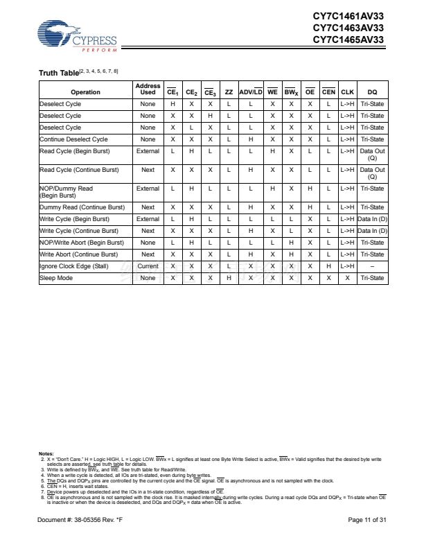
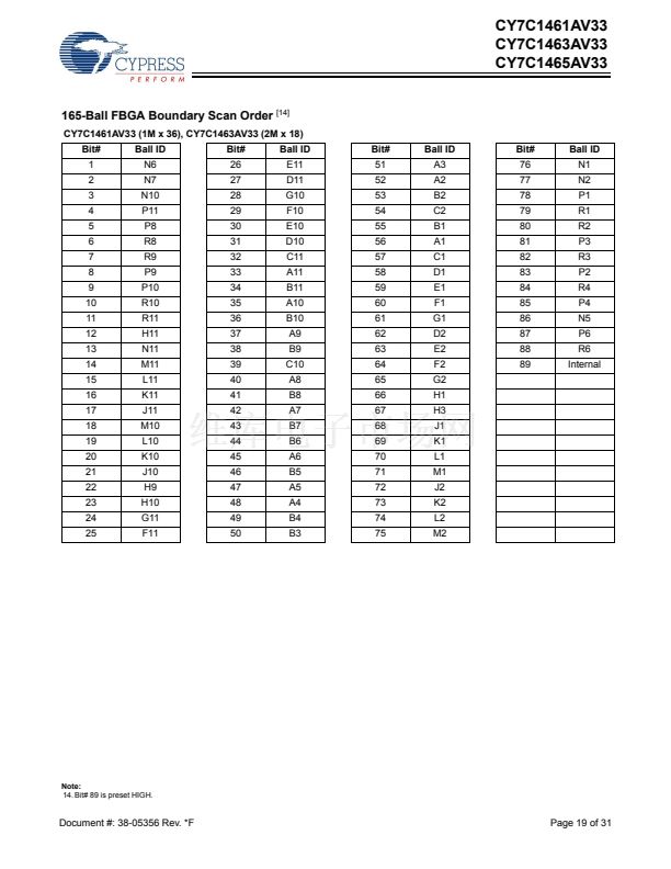
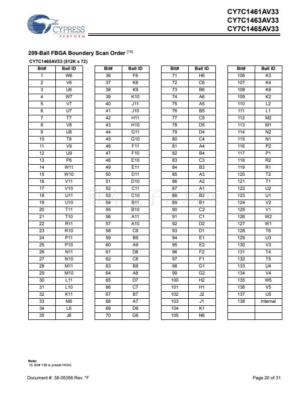
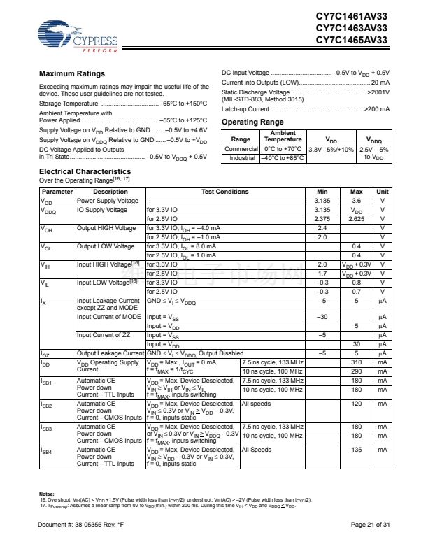
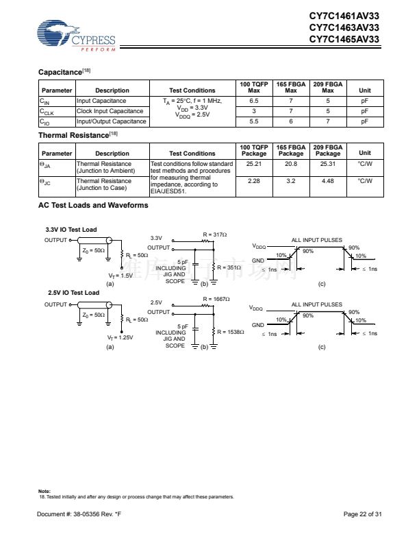
Notes:
2. X = 鈥淒on't Care.鈥?H = Logic HIGH, L = Logic LOW. BWx = L signifies at least one Byte Write Select is active, BWx = Valid signifies that the desired byte write
selects are asserted, see truth table for details.
3. Write is defined by BW
X
, and WE. See truth table for Read/Write.
4. When a write cycle is detected, all IOs are tri-stated, even during byte writes.
5. The DQs and DQP
X
pins are controlled by the current cycle and the OE signal. OE is asynchronous and is not sampled with the clock.
6. CEN = H, inserts wait states.
7. Device powers up deselected and the IOs in a tri-state condition, regardless of OE.
8. OE is asynchronous and is not sampled with the clock rise. It is masked internally during write cycles. During a read cycle DQs and DQP
X
= Tri-state when OE
is inactive or when the device is deselected, and DQs and DQP
X
= data when OE is active.
Document #: 38-05356 Rev. *F
Page 11 of 31


 1
1
 2
2
 3
3
 4
4
 5
5
 6
6
 7
7
 8
8
 9
9
 10
10
 11
11
 12
12
 13
13
 14
14
 15
15
 16
16
 17
17
 18
18
 19
19
 20
20
 21
21
 22
22
 23
23
 24
24
 25
25
 26
26
 27
27
 28
28
 29
29
 30
30
 31
31
