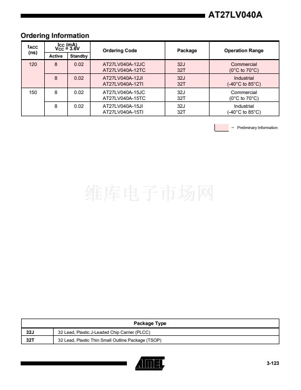
PLCC and TSOP packages. All devices feature two-line
bus contention.
= 5.0V. The device is also
are pluggable in both 3-volt and 5-volt hosts.
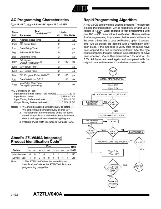
high quality and efficient production use. The Rapid
鈩?/div>
Pro-
gramming Algorithm reduces the time required to program
the part and guarantees reliable programming. Program-
ming time is typically only 100
碌s/byte.
The Integrated
Product Identification Code electronically identifies the de-
vice and manufacturer. This feature is used by industry
standard programming equipment to select the proper
programming algorithms and voltages. The AT27LV040A
programs exactly the same way as a standard 5V
AT27C040 and uses the same programming equipment.
System Considerations
Switching between active and standby conditions via the
Chip Enable pin may produce transient voltage excur-
sions. Unless accommodated by the system design, these
transients may exceed data sheet limits, resulting in de-
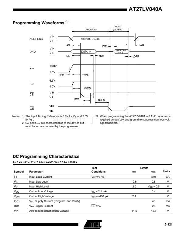
vice non-conformance. At a minimum, a 0.1
碌F
high fre-
quency, low inherent inductance, ceramic capacitor
should be utilized for each device. This capacitor should
be connected between the V
CC
and Ground terminals of
the device, as close to the device as possible. Additionally,
to stabilize the supply voltage level on printed circuit
boards with large EPROM arrays, a 4.7
碌F
bulk electrolytic
capacitor should be utilized, again connected between the
V
CC
and Ground terminals. This capacitor should be posi-
tioned as close as possible to the point where the power
supply is connected to the array.
3-116
AT27LV040A


 1
1
 2
2
 3
3
 4
4
 5
5
 6
6
 7
7
 8
8
 9
9
