ADSP-2185L
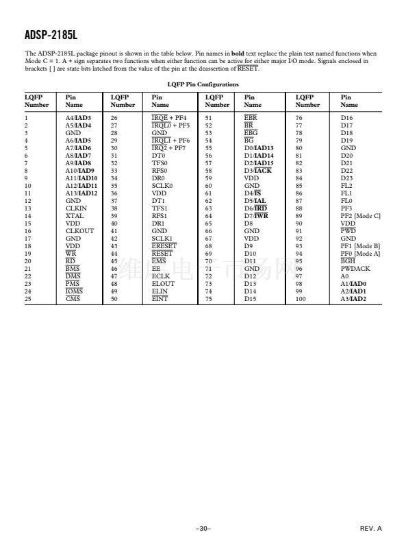
Pin Terminations (Continued)
Pin
Name
D4 or
IS
D3 or
IACK
D2:0 or
IAD15:13
PMS
DMS
BMS
IOMS
CMS
RD
WR
BR
BG
BGH
IRQ2/PF7
I/O
3-State
(Z)
I/O (Z)
I
I/O (Z)
I/O (Z)
I/O (Z)
O (Z)
O (Z)
O (Z)
O (Z)
O (Z)
O (Z)
O (Z)
I
O (Z)
O
I/O (Z)
Reset
State
Hi-Z
I
Hi-Z
Hi-Z
Hi-Z
O
O
O
O
O
O
O
I
O
O
I
Hi-Z*
Caused
By
Unused
Configuration
Interrupts
IRQL1/PF6
I/O (Z)
I
IRQL0/PF5
I/O (Z)
I
IRQE/PF4
I/O (Z)
I
SCLK0
RFS0
DR0
TFS0
DT0
SCLK1
RFS1/RQ0
DR1/FI
TFS1/RQ1
DT1/FO
EE
EBR
EBG
ERESET
EMS
EINT
ECLK
ELIN
ELOUT
I/O
I/O
I
I/O
O
I/O
I/O
I
I/O
O
I
I
O
I
O
I
I
I
O
I
I
I
O
O
I
I
I
O
O
I
I
O
I
O
I
I
I
O
BR, EBR
Float
High (Inactive)
BR, EBR
Float
Float
BR, EBR
Float
IS
Float
BR, EBR Float
BR, EBR
Float
BR, EBR
Float
BR, EBR
Float
BR, EBR
Float
BR, EBR
Float
BR, EBR
Float
High (Inactive)
EE
Float
Float
Input = High (Inactive)
or Program as Output,
Set to 1, Let Float
Input = High (Inactive)
or Program as Output,
Set to 1, Let Float
Input = High (Inactive)
or Program as Output,
Set to 1, Let Float
Input = High (Inactive)
or Program as Output,
Set to 1, Let Float
Input = High or Low,
Output = Float
High or Low
High or Low
High or Low
Float
Input = High or Low,
Output = Float
High or Low
High or Low
High or Low
Float
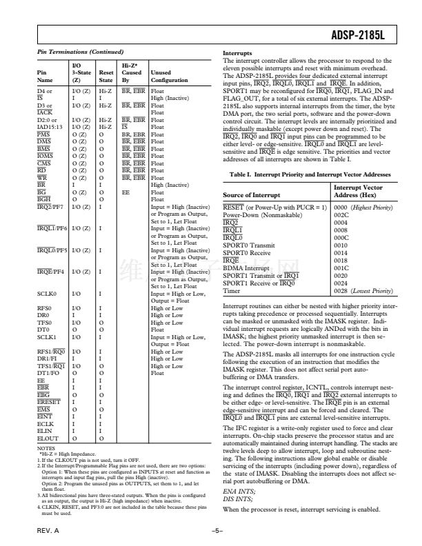
The interrupt controller allows the processor to respond to the
eleven possible interrupts and reset with minimum overhead.
The ADSP-2185L provides four dedicated external interrupt
input pins,
IRQ2, IRQL0, IRQL1
and
IRQE.
In addition,
SPORT1 may be reconfigured for
IRQ0, IRQ1,
FLAG_IN and
FLAG_OUT, for a total of six external interrupts. The ADSP-
2185L also supports internal interrupts from the timer, the byte
DMA port, the two serial ports, software and the power-down
control circuit. The interrupt levels are internally prioritized and
individually maskable (except power down and reset). The
IRQ2, IRQ0
and
IRQ1
input pins can be programmed to be
either level- or edge-sensitive.
IRQL0
and
IRQL1
are level-
sensitive and
IRQE
is edge sensitive. The priorities and vector
addresses of all interrupts are shown in Table I.
Table I. Interrupt Priority and Interrupt Vector Addresses
Source of Interrupt
RESET
(or Power-Up with PUCR = 1)
Power-Down (Nonmaskable)
IRQ2
IRQL1
IRQL0
SPORT0 Transmit
SPORT0 Receive
IRQE
BDMA Interrupt
SPORT1 Transmit or
IRQ1
SPORT1 Receive or
IRQ0
Timer
Interrupt Vector
Address (Hex)
0000 (Highest
Priority)
002C
0004
0008
000C
0010
0014
0018
001C
0020
0024
0028 (Lowest
Priority)
Interrupt routines can either be nested with higher priority inter-
rupts taking precedence or processed sequentially. Interrupts
can be masked or unmasked with the IMASK register. Indi-
vidual interrupt requests are logically ANDed with the bits in
IMASK; the highest priority unmasked interrupt is then se-
lected. The power-down interrupt is nonmaskable.
The ADSP-2185L masks all interrupts for one instruction cycle
following the execution of an instruction that modifies the
IMASK register. This does not affect serial port auto-
buffering or DMA transfers.
The interrupt control register, ICNTL, controls interrupt nest-
ing and defines the
IRQ0, IRQ1
and
IRQ2
external interrupts to
be either edge- or level-sensitive. The
IRQE
pin is an external
edge-sensitive interrupt and can be forced and cleared. The
IRQL0
and
IRQL1
pins are external level-sensitive interrupts.
The IFC register is a write-only register used to force and clear
interrupts. On-chip stacks preserve the processor status and are
automatically maintained during interrupt handling. The stacks are
twelve levels deep to allow interrupt, loop and subroutine nest-
ing. The following instructions allow global enable or disable
servicing of the interrupts (including power down), regardless of
the state of IMASK. Disabling the interrupts does not affect se-
rial port autobuffering or DMA.
ENA INTS;
DIS INTS;
When the processor is reset, interrupt servicing is enabled.
鈥?鈥?/div>
NOTES
**Hi-Z
= High Impedance.
1. If the CLKOUT pin is not used, turn it OFF.
2. If the Interrupt/Programmable Flag pins are not used, there are two options:
Option 1: When these pins are configured as INPUTS at reset and function as
interrupts and input flag pins, pull the pins High (inactive).
Option 2: Program the unused pins as OUTPUTS, set them to 1, and let
them float.
3. All bidirectional pins have three-stated outputs. When the pins is configured
as an output, the output is Hi-Z (high impedance) when inactive.
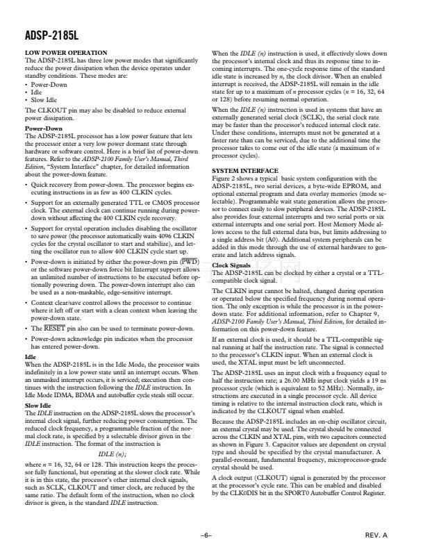
4. CLKIN, RESET, and PF3:0 are not included in the table because these pins
must be used.
REV. A


 1
1
 2
2
 3
3
 4
4
 5
5
 6
6
 7
7
 8
8
 9
9
 10
10
 11
11
 12
12
 13
13
 14
14
 15
15
 16
16
 17
17
 18
18
 19
19
 20
20
 21
21
 22
22
 23
23
 24
24
 25
25
 26
26
 27
27
 28
28
 29
29
 30
30
 31
31
