PIC16C64X & PIC16C66X
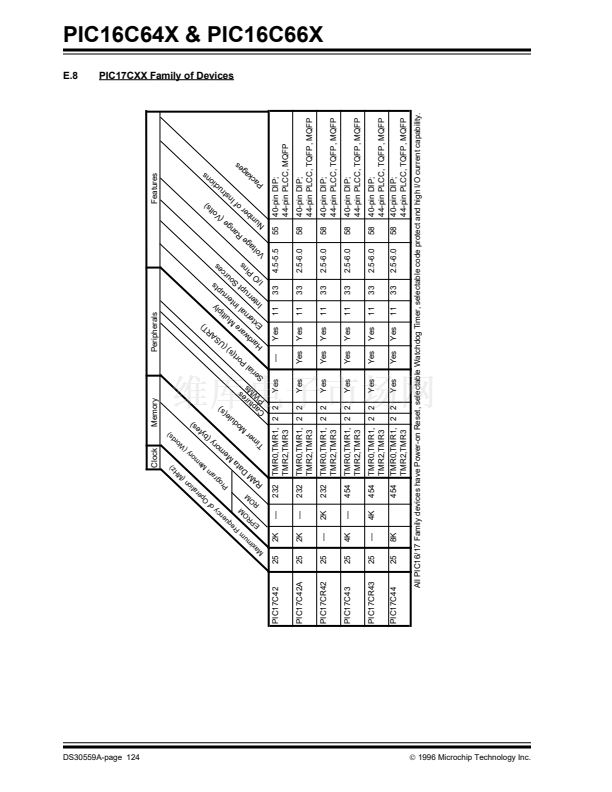
4.0
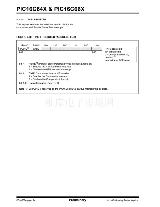
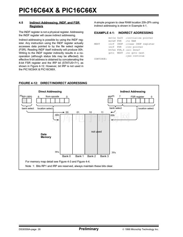
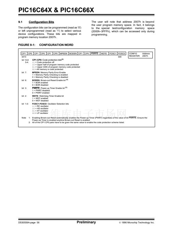
4.1
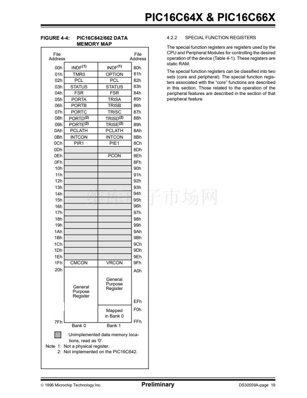
MEMORY ORGANIZATION
Program Memory Organization
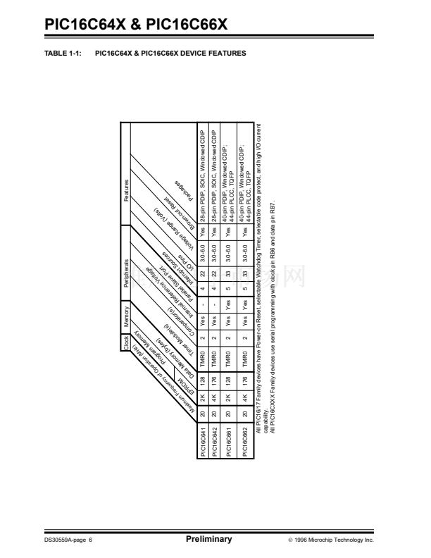
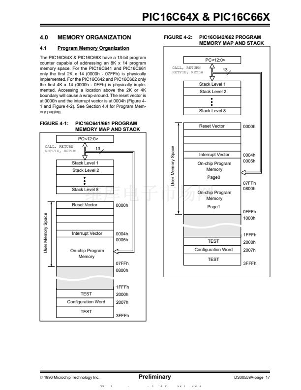
FIGURE 4-2:
PIC16C642/662 PROGRAM
MEMORY MAP AND STACK
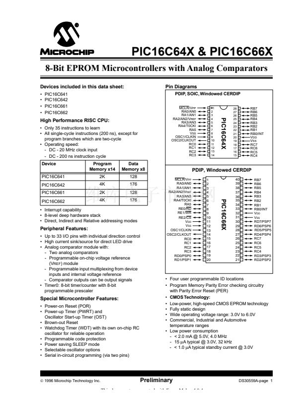
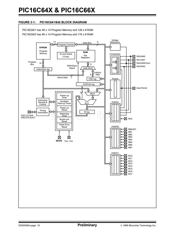
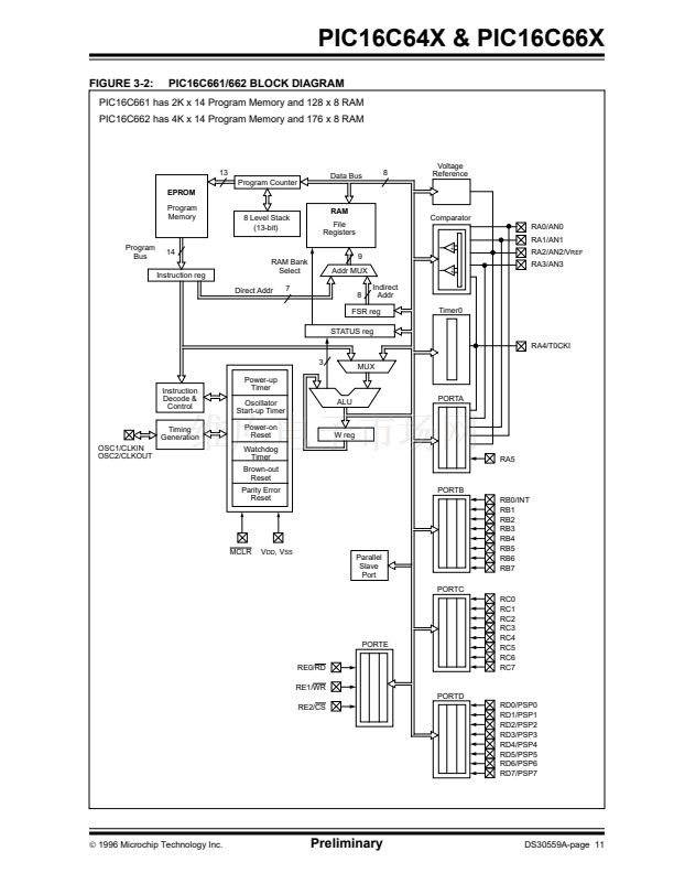
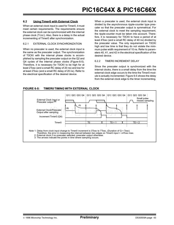
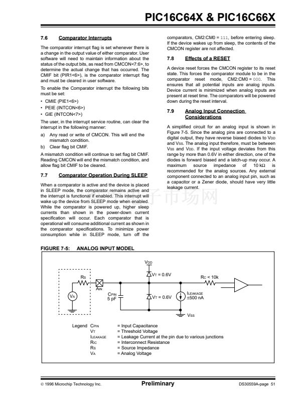
The PIC16C64X & PIC16C66X have a 13-bit program
counter capable of addressing an 8K x 14 program
memory space. For the PIC16C641 and PIC16C661
only the 铿乺st 2K x 14 (0000h - 07FFh) is physically
implemented. For the PIC16C642 and PIC16C662 only
the 铿乺st 4K x 14 (0000h - 0FFh) is physically imple-
mented. Accessing a location above the 2K or 4K
boundary will cause a wrap-around. The reset vector is
at 0000h and the interrupt vector is at 0004h (Figure 4-
1 and Figure 4-2). See Section 4.4 for Program Mem-
ory paging.
PC<12:0>
CALL, RETURN
RETFIE, RETLW
13
Stack Level 1
Stack Level 2
Stack Level 8
Reset Vector
FIGURE 4-1:
PIC16C641/661 PROGRAM
MEMORY MAP AND STACK
PC<12:0>
13
User Memory Space
0000h
CALL, RETURN
RETFIE, RETLW
Interrupt Vector
On-chip Program
Memory
Page0
Stack Level 1
Stack Level 2
0004h
0005h
Stack Level 8
Reset Vector
User Memory Space
On-chip Program
Memory
0000h
Page1
07FFh
0800h
0FFFh
1000h
Interrupt Vector
0004h
0005h
1FFFh
TEST
Con铿乬uration Word
2000h
2007h
3FFFh
On-chip Program
Memory
07FFh
0800h
TEST
1FFFh
TEST
Con铿乬uration Word
TEST
2000h
2007h
3FFFh
漏
1996 Microchip Technology Inc.
Preliminary
This document was created with FrameMaker 4 0 4
DS30559A-page 17


 1
1
 2
2
 3
3
 4
4
 5
5
 6
6
 7
7
 8
8
 9
9
 10
10
 11
11
 12
12
 13
13
 14
14
 15
15
 16
16
 17
17
 18
18
 19
19
 20
20
 21
21
 22
22
 23
23
 24
24
 25
25
 26
26
 27
27
 28
28
 29
29
 30
30
 31
31
 32
32
 33
33
 34
34
 35
35
 36
36
 37
37
 38
38
 39
39
 40
40
 41
41
 42
42
 43
43
 44
44
 45
45
 46
46
 47
47
 48
48
 49
49
 50
50
 51
51
 52
52
 53
53
 54
54
 55
55
 56
56
 57
57
 58
58
 59
59
 60
60
 61
61
 62
62
 63
63
 64
64
 65
65
 66
66
 67
67
 68
68
 69
69
 70
70
 71
71
 72
72
 73
73
 74
74
 75
75
 76
76
 77
77
 78
78
 79
79
 80
80
 81
81
 82
82
 83
83
 84
84
 85
85
 86
86
 87
87
 88
88
 89
89
 90
90
 91
91
 92
92
 93
93
 94
94
 95
95
 96
96
 97
97
 98
98
 99
99
 100
100
 101
101
 102
102
 103
103
 104
104
 105
105
 106
106
 107
107
 108
108
 109
109
 110
110
 111
111
 112
112
 113
113
 114
114
 115
115
 116
116
 117
117
 118
118
 119
119
 120
120
 121
121
 122
122
 123
123
 124
124
 125
125
 126
126
 127
127
 128
128
 129
129
 130
130
 131
131
 132
132
 133
133
 134
134
 135
135
 136
136
