PIC16C64X & PIC16C66X
9.1
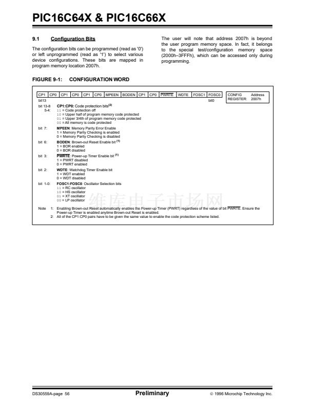
Con铿乬uration Bits
The con铿乬uration bits can be programmed (read as '0')
or left unprogrammed (read as '1') to select various
device con铿乬urations. These bits are mapped in
program memory location 2007h.
The user will note that address 2007h is beyond
the user program memory space. In fact, it belongs
to the special test/con铿乬uration memory space
(2000h鈥?FFFh), which can be accessed only during
programming.
FIGURE 9-1:
CP1
bit13
bit 13-8
5-4:
CP0
CP1
CONFIGURATION WORD
CP0
CP1
CP0
MPEEN
(2)
BODEN CP1
CP0
PWRTE
WDTE
FOSC1 FOSC0
bit0
CONFIG
REGISTER:
Address
2007h
CP1:CP0:
Code protection bits
11
= Code protection off
10
= Upper half of program memory code protected
01
= Upper 3/4th of program memory code protected
00
= All memory is code protected
MPEEN
: Memory Parity Error Enable
1 = Memory Parity Checking is enabled
0 = Memory Parity Checking is disabled
BODEN
: Brown-out Reset Enable bit
(1)
1 = BOR enabled
0 = BOR disabled
PWRTE
: Power-up Timer Enable bit
(1)
1 = PWRT disabled
0 = PWRT enabled
WDTE
: Watchdog Timer Enable bit
1 = WDT enabled
0 = WDT disabled
FOSC1:FOSC0
: Oscillator Selection bits
11
= RC oscillator
10
= HS oscillator
01
= XT oscillator
00
= LP oscillator
1: Enabling Brown-out Reset automatically enables the Power-up Timer (PWRT) regardless of the value of bit PWRTE. Ensure the
Power-up Timer is enabled anytime Brown-out Reset is enabled.
2: All of the CP1:CP0 pairs have to be given the same value to enable the code protection scheme listed.
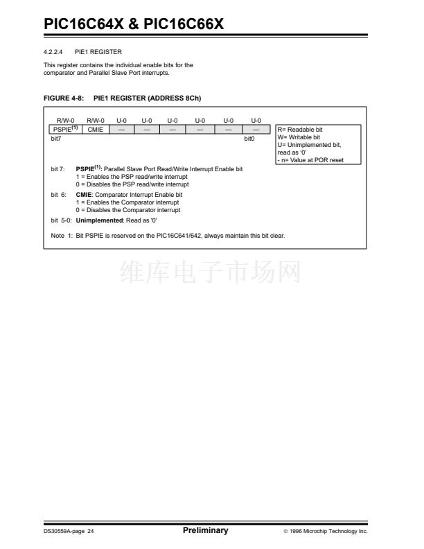
bit 7:
bit 6:
bit 3:
bit 2:
bit 1-0:
Note
DS30559A-page 56
Preliminary
漏
1996 Microchip Technology Inc.


 1
1
 2
2
 3
3
 4
4
 5
5
 6
6
 7
7
 8
8
 9
9
 10
10
 11
11
 12
12
 13
13
 14
14
 15
15
 16
16
 17
17
 18
18
 19
19
 20
20
 21
21
 22
22
 23
23
 24
24
 25
25
 26
26
 27
27
 28
28
 29
29
 30
30
 31
31
 32
32
 33
33
 34
34
 35
35
 36
36
 37
37
 38
38
 39
39
 40
40
 41
41
 42
42
 43
43
 44
44
 45
45
 46
46
 47
47
 48
48
 49
49
 50
50
 51
51
 52
52
 53
53
 54
54
 55
55
 56
56
 57
57
 58
58
 59
59
 60
60
 61
61
 62
62
 63
63
 64
64
 65
65
 66
66
 67
67
 68
68
 69
69
 70
70
 71
71
 72
72
 73
73
 74
74
 75
75
 76
76
 77
77
 78
78
 79
79
 80
80
 81
81
 82
82
 83
83
 84
84
 85
85
 86
86
 87
87
 88
88
 89
89
 90
90
 91
91
 92
92
 93
93
 94
94
 95
95
 96
96
 97
97
 98
98
 99
99
 100
100
 101
101
 102
102
 103
103
 104
104
 105
105
 106
106
 107
107
 108
108
 109
109
 110
110
 111
111
 112
112
 113
113
 114
114
 115
115
 116
116
 117
117
 118
118
 119
119
 120
120
 121
121
 122
122
 123
123
 124
124
 125
125
 126
126
 127
127
 128
128
 129
129
 130
130
 131
131
 132
132
 133
133
 134
134
 135
135
 136
136
