鈩?/div>
.
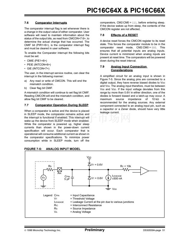
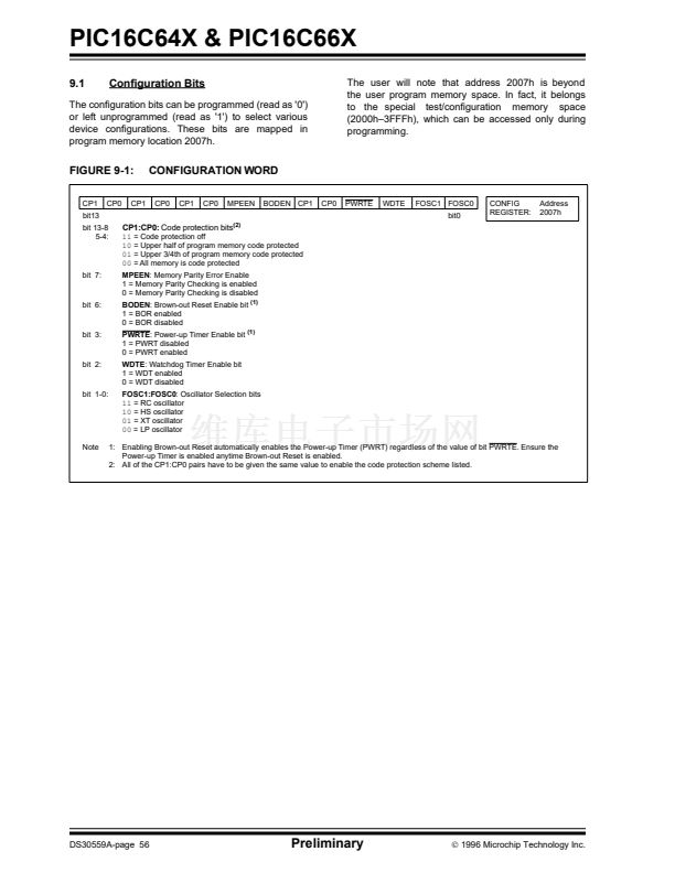
Although the oscillator will operate with no external
capacitor (Cext = 0 pF), we recommend using values
above 20 pF for noise and stability reasons. With no or
small external capacitance, the oscillation frequency
can vary dramatically due to changes in external
capacitances, such as PCB trace capacitance or pack-
age lead frame capacitance.
See characterization data for desired device for RC fre-
quency variation from part to part due to normal pro-
cess variation. The variation is larger for larger R (since
leakage current variation will affect RC frequency more
for large R) and for smaller C (since variation of input
capacitance will affect RC frequency more).
See characterization data for desired device for varia-
tion of oscillator frequency due to V
DD
for given Rext/
Cext values as well as frequency variation due to oper-
ating temperature for given R, C, and V
DD
values.
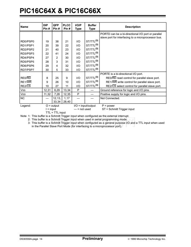
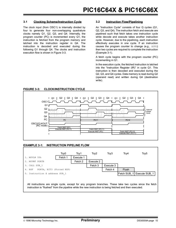
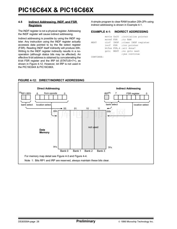
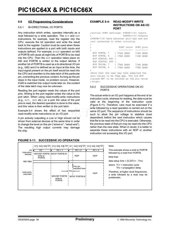
The oscillator frequency, divided by 4, is available on
the OSC2/CLKOUT pin, and can be used for test pur-
poses or to synchronize other logic (see Figure 3-3 for
waveform).
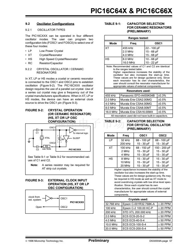
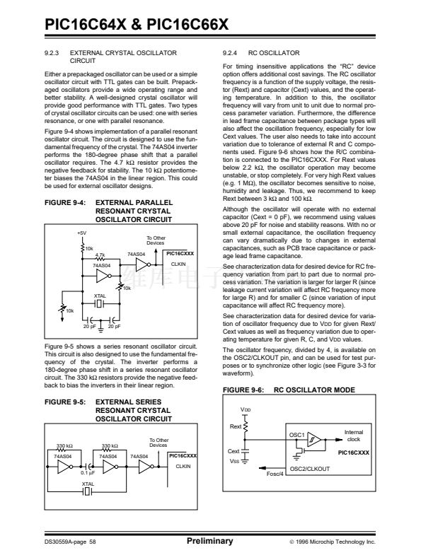
Either a prepackaged oscillator can be used or a simple
oscillator circuit with TTL gates can be built. Prepack-
aged oscillators provide a wide operating range and
better stability. A well-designed crystal oscillator will
provide good performance with TTL gates. Two types
of crystal oscillator circuits can be used: one with series
resonance, or one with parallel resonance.
Figure 9-4 shows implementation of a parallel resonant
oscillator circuit. The circuit is designed to use the fun-
damental frequency of the crystal. The 74AS04 inverter
performs the 180-degree phase shift that a parallel
oscillator requires. The 4.7 k
鈩?/div>
resistor provides the
negative feedback for stability. The 10 k
鈩?/div>
potentiome-
ter biases the 74AS04 in the linear region. This could
be used for external oscillator designs.
FIGURE 9-4:
EXTERNAL PARALLEL
RESONANT CRYSTAL
OSCILLATOR CIRCUIT
To Other
Devices
+5V
10k
4.7k
74AS04
74AS04
PIC16CXXX
CLKIN
10k
XTAL
10k
20 pF
20 pF
Figure 9-5 shows a series resonant oscillator circuit.
This circuit is also designed to use the fundamental fre-
quency of the crystal. The inverter performs a
180-degree phase shift in a series resonant oscillator
circuit. The 330 k
鈩?/div>
resistors provide the negative feed-
back to bias the inverters in their linear region.
FIGURE 9-6:
V
DD
Rext
RC OSCILLATOR MODE
FIGURE 9-5:
EXTERNAL SERIES
RESONANT CRYSTAL
OSCILLATOR CIRCUIT
To Other
Devices
74AS04
PIC16CXXX
CLKIN
OSC1
330 k鈩?/div>
74AS04
0.1
碌F
XTAL
330 k鈩?/div>
74AS04
Internal
clock
PIC16CXXX
Cext
V
SS
Fosc/4
OSC2/CLKOUT
DS30559A-page 58
Preliminary
漏
1996 Microchip Technology Inc.
PIC16C641 PDF文件相关型号
PIC16C642
PIC16C641相关型号PDF文件下载
-
型号
版本
描述
厂商
下载
-
英文版
8-Pin FLASH-Based 8-Bit CMOS Microcontrollers
-
英文版
8-Pin, 8-Bit CMOS Microcontroller with EEPROM Data Memory
MICROCHIP ...
-
英文版
8-Pin, 8-Bit CMOS Microcontroller with A/D Converter and EEP...
MICROCHIP ...
-
英文版
8-Pin, 8-Bit CMOS Microcontrollers
MICROCHIP ...
-
英文版
EPROM Memory Programming Specification
MICROCHIP ...
-
英文版
8-Pin FLASH-Based 8-Bit CMOS Microcontrollers
MICROCHIP ...
-
英文版
Microcontroller
-
英文版
Microcontroller
-
英文版
Microcontroller
ETC
-
英文版
EPROM-Based 8-Bit CMOS Microcontroller
-
英文版
8-Pin, 8-Bit CMOS Microcontrollers
-
英文版
8-Pin, 8-Bit CMOS Microcontrollers
MICROCHIP ...
-
英文版
ETC
-
英文版
EPROM Memory Programming Specification
-
英文版
EPROM Memory Programming Specification
MICROCHIP ...
-
英文版
28-Pin Programmable Mixed Signal Controller
-
英文版
EPROM Memory Programming Specification
-
英文版
Microcontroller
ETC
-
英文版
Microcontroller
ETC
-
英文版
EPROM/ROM-Based 8-Bit CMOS Microcontroller Series


 1
1
 2
2
 3
3
 4
4
 5
5
 6
6
 7
7
 8
8
 9
9
 10
10
 11
11
 12
12
 13
13
 14
14
 15
15
 16
16
 17
17
 18
18
 19
19
 20
20
 21
21
 22
22
 23
23
 24
24
 25
25
 26
26
 27
27
 28
28
 29
29
 30
30
 31
31
 32
32
 33
33
 34
34
 35
35
 36
36
 37
37
 38
38
 39
39
 40
40
 41
41
 42
42
 43
43
 44
44
 45
45
 46
46
 47
47
 48
48
 49
49
 50
50
 51
51
 52
52
 53
53
 54
54
 55
55
 56
56
 57
57
 58
58
 59
59
 60
60
 61
61
 62
62
 63
63
 64
64
 65
65
 66
66
 67
67
 68
68
 69
69
 70
70
 71
71
 72
72
 73
73
 74
74
 75
75
 76
76
 77
77
 78
78
 79
79
 80
80
 81
81
 82
82
 83
83
 84
84
 85
85
 86
86
 87
87
 88
88
 89
89
 90
90
 91
91
 92
92
 93
93
 94
94
 95
95
 96
96
 97
97
 98
98
 99
99
 100
100
 101
101
 102
102
 103
103
 104
104
 105
105
 106
106
 107
107
 108
108
 109
109
 110
110
 111
111
 112
112
 113
113
 114
114
 115
115
 116
116
 117
117
 118
118
 119
119
 120
120
 121
121
 122
122
 123
123
 124
124
 125
125
 126
126
 127
127
 128
128
 129
129
 130
130
 131
131
 132
132
 133
133
 134
134
 135
135
 136
136
