鈥?/div>
Read Memory
Erase Memory
Program Memory
Blank Check
Read Executive Firmware Revision
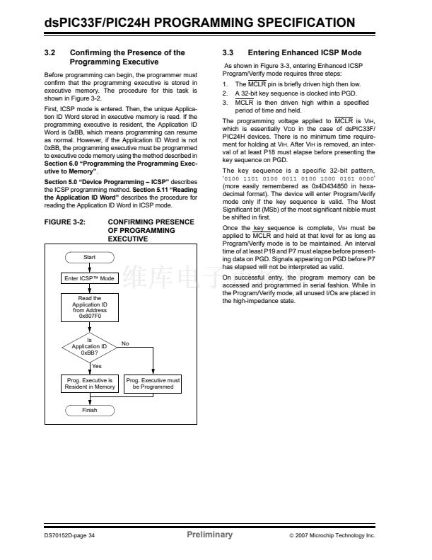
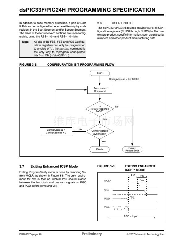
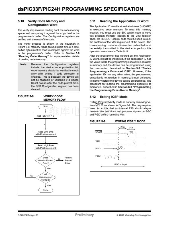
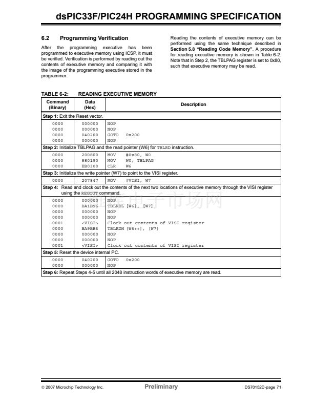
Figure 3-1 shows the high-level overview of the
programming process. After entering Enhanced ICSP
mode, the programming executive is verified. Next, the
device is erased. Then, the code memory is pro-
grammed, followed by the nonvolatile device Configu-
ration registers. Code memory (including the
Configuration registers) is then verified to ensure that
programming was successful.
After the programming executive has been verified
in memory (or loaded if not present), the dsPIC33F/
PIC24H Programming Specification can be pro-
grammed using the command set shown in Table 3-1.
FIGURE 3-1:
HIGH-LEVEL ENHANCED
ICSP鈩?PROGRAMMING
FLOW
Start
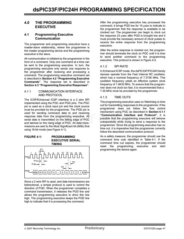
The programming executive performs the low-level
tasks required for erasing, programming and verifying
a device. This allows the programmer to program the
device by issuing the appropriate commands and data.
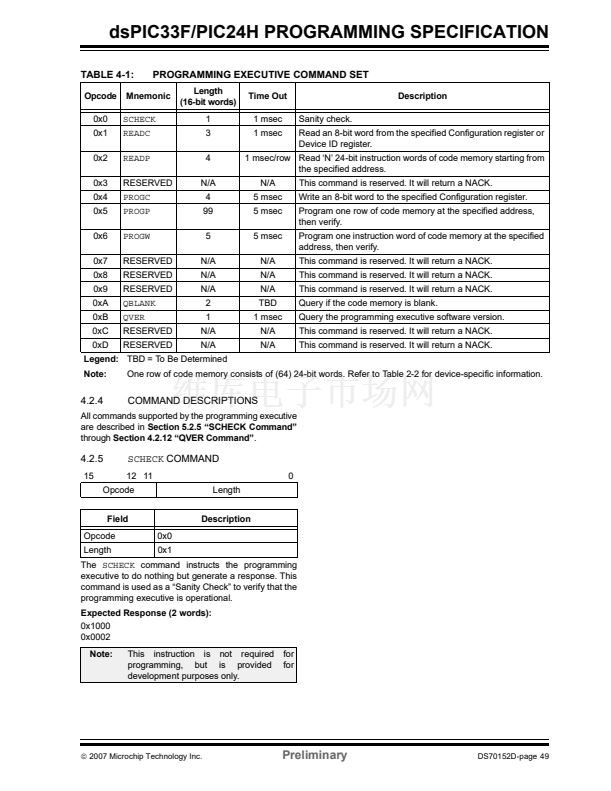
Table 3-1 summarizes the commands. A detailed
description for each command is provided in
Section 4.2 鈥淧rogramming Executive Commands鈥?
Enter Enhanced ICSP鈩?/div>
Perform Bulk
Erase
TABLE 3-1:
Command
SCHECK
READC
READP
PROGC
PROGP
PROGW
QBLANK
QVER
COMMAND SET SUMMARY
Description
Sanity check
Read Configuration registers or Device
ID registers
Read code memory
Program a Configuration register and
verify
Program one row of code memory and
verify
Program one word of code memory
and verify
Query if the code memory is blank
Query the software version
Done
Exit Enhanced ICSP
Program Configuration Bits
Verify Program
Program Memory
Verify Configuration Bits
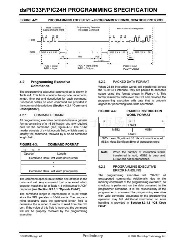
The programming executive uses the device鈥檚 data
RAM for variable storage and program execution. After
the programming executive has run, no assumptions
should be made about the contents of data RAM.
漏
2007 Microchip Technology Inc.
Preliminary
DS70152D-page 33


 1
1
 2
2
 3
3
 4
4
 5
5
 6
6
 7
7
 8
8
 9
9
 10
10
 11
11
 12
12
 13
13
 14
14
 15
15
 16
16
 17
17
 18
18
 19
19
 20
20
 21
21
 22
22
 23
23
 24
24
 25
25
 26
26
 27
27
 28
28
 29
29
 30
30
 31
31
 32
32
 33
33
 34
34
 35
35
 36
36
 37
37
 38
38
 39
39
 40
40
 41
41
 42
42
 43
43
 44
44
 45
45
 46
46
 47
47
 48
48
 49
49
 50
50
 51
51
 52
52
 53
53
 54
54
 55
55
 56
56
 57
57
 58
58
 59
59
 60
60
 61
61
 62
62
 63
63
 64
64
 65
65
 66
66
 67
67
 68
68
 69
69
 70
70
 71
71
 72
72
 73
73
 74
74
 75
75
 76
76
 77
77
 78
78
 79
79
 80
80
