dsPIC33F/PIC24H PROGRAMMING SPECIFICATION
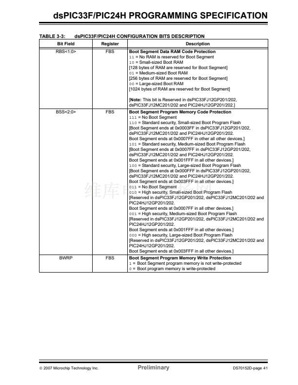
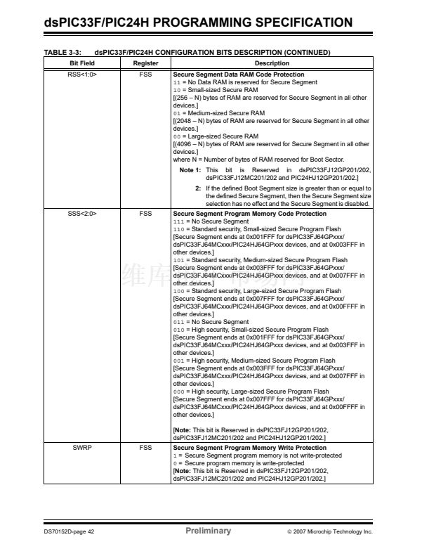
In addition to code memory protection, a part of Data
RAM can be configured to be accessible only by code
resident in the Boot Segment and/or Secure Segment.
The sizes of these 鈥渞eserved鈥?sections are user-config-
urable, using the RBS<1:0> and RSS<1:0> bits.
Note:
All bits in the FBS, FSS and FGS Configu-
ration registers can only be programmed
to a value of 鈥?鈥? the
ERASEB
command is
the only way to reprogram code-protect
bits from ON (鈥?鈥? to OFF (鈥?鈥?.
3.6.5
USER UNIT ID
The dsPIC33F/PIC24H devices provide four 8-bit Con-
figuration registers (FUID0 through FUID3) for the user
to store product-specific information, such as unit serial
numbers and other product manufacturing data.
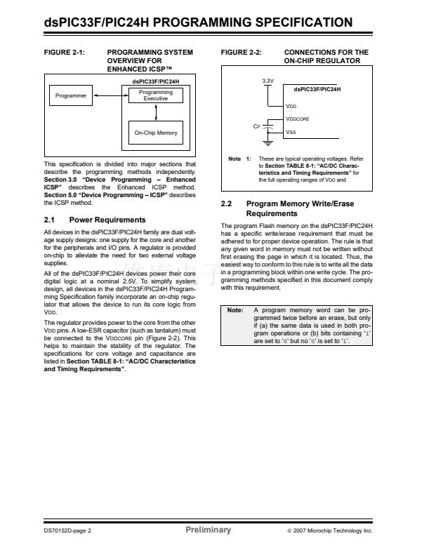
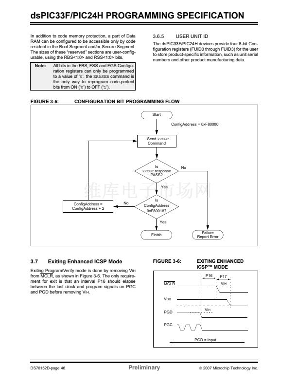
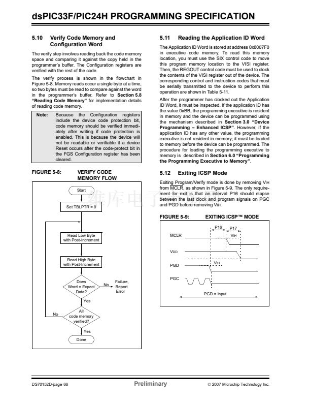
FIGURE 3-5:
CONFIGURATION BIT PROGRAMMING FLOW
Start
ConfigAddress = 0xF80000
Send
PROGC
Command
Is
PROGC
response
PASS?
Yes
Is
ConfigAddress
0xF80018?
Yes
Finish
No
ConfigAddress =
ConfigAddress + 2
No
Failure
Report Error
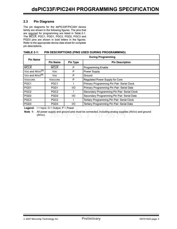
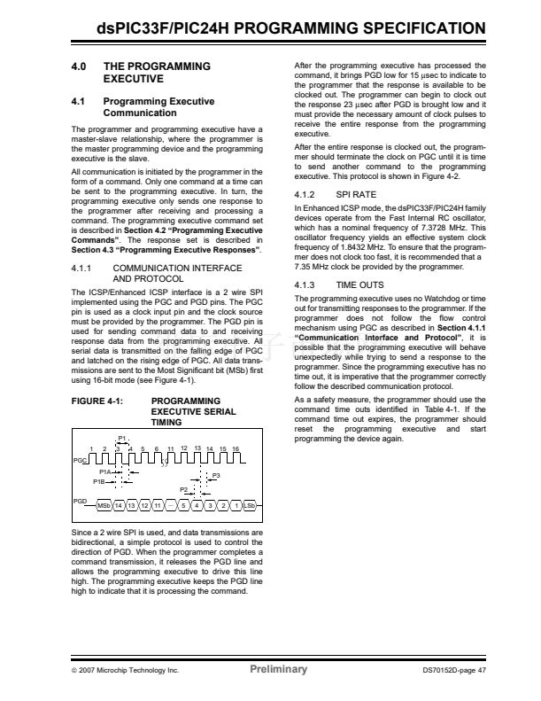
3.7
Exiting Enhanced ICSP Mode
FIGURE 3-6:
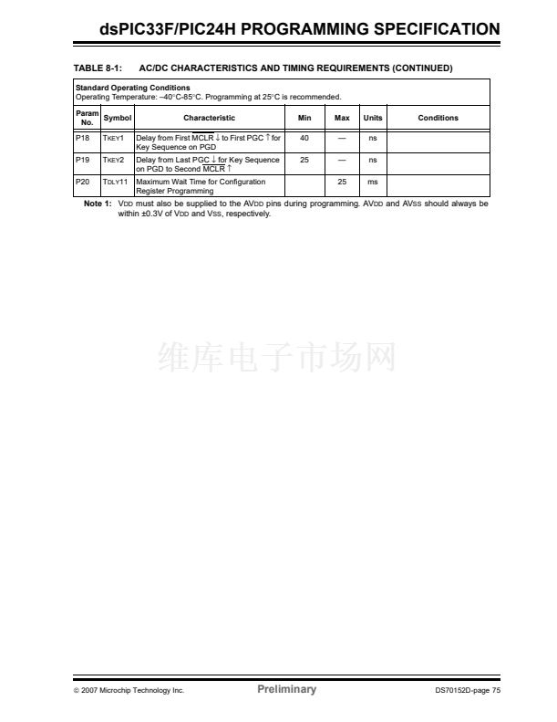
Exiting Program/Verify mode is done by removing V
IH
from MCLR, as shown in Figure 3-6. The only require-
ment for exit is that an interval P16 should elapse
between the last clock and program signals on PGC
and PGD before removing V
IH
.
EXITING ENHANCED
ICSP鈩?MODE
P16
P17
V
IH
MCLR
V
DD
PGD
PGC
V
IH
PGD = Input
DS70152D-page 46
Preliminary
漏
2007 Microchip Technology Inc.


 1
1
 2
2
 3
3
 4
4
 5
5
 6
6
 7
7
 8
8
 9
9
 10
10
 11
11
 12
12
 13
13
 14
14
 15
15
 16
16
 17
17
 18
18
 19
19
 20
20
 21
21
 22
22
 23
23
 24
24
 25
25
 26
26
 27
27
 28
28
 29
29
 30
30
 31
31
 32
32
 33
33
 34
34
 35
35
 36
36
 37
37
 38
38
 39
39
 40
40
 41
41
 42
42
 43
43
 44
44
 45
45
 46
46
 47
47
 48
48
 49
49
 50
50
 51
51
 52
52
 53
53
 54
54
 55
55
 56
56
 57
57
 58
58
 59
59
 60
60
 61
61
 62
62
 63
63
 64
64
 65
65
 66
66
 67
67
 68
68
 69
69
 70
70
 71
71
 72
72
 73
73
 74
74
 75
75
 76
76
 77
77
 78
78
 79
79
 80
80
