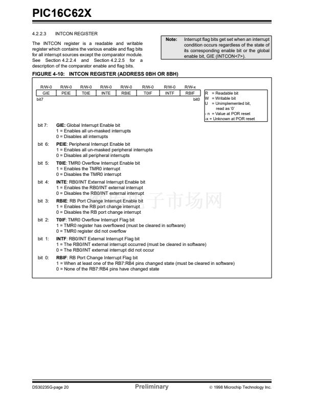
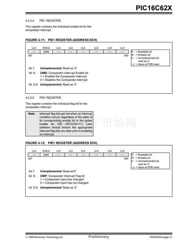
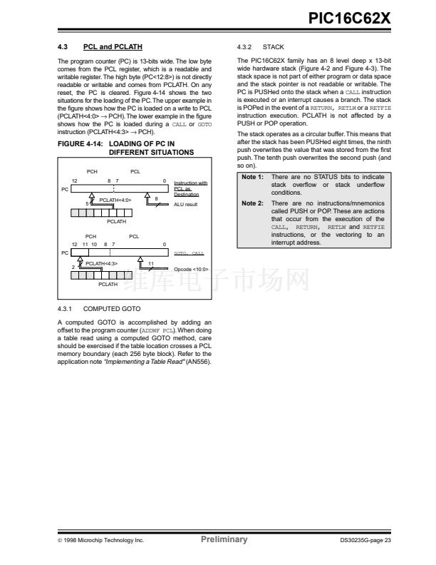
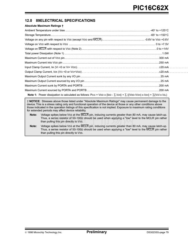
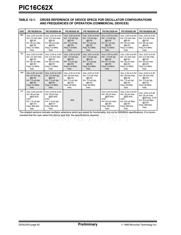
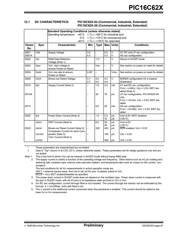
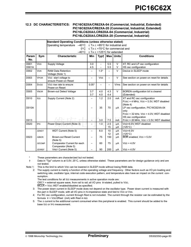
PIC16C62X
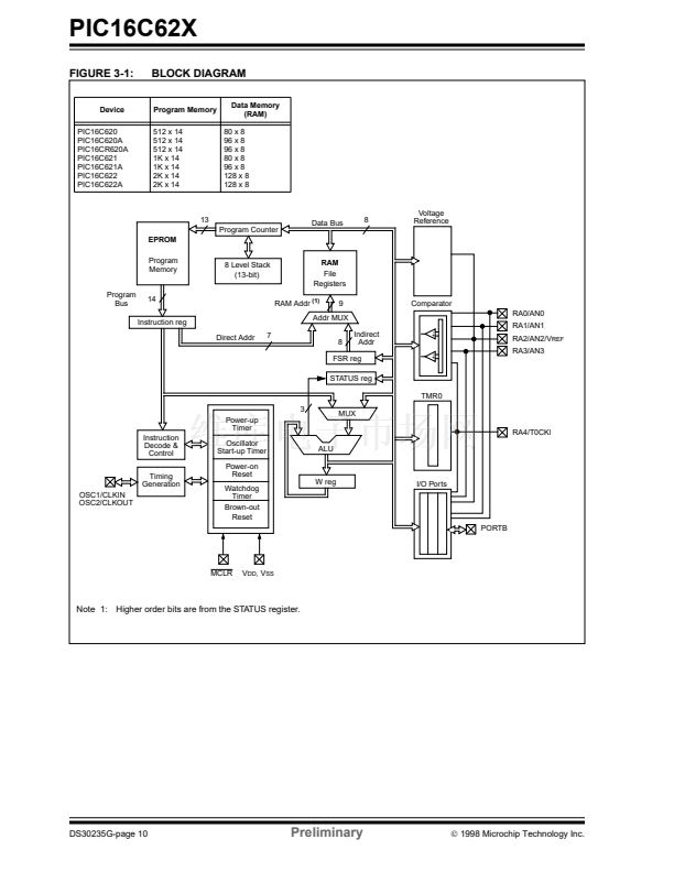
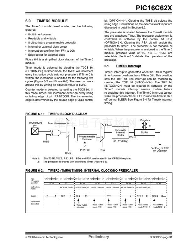
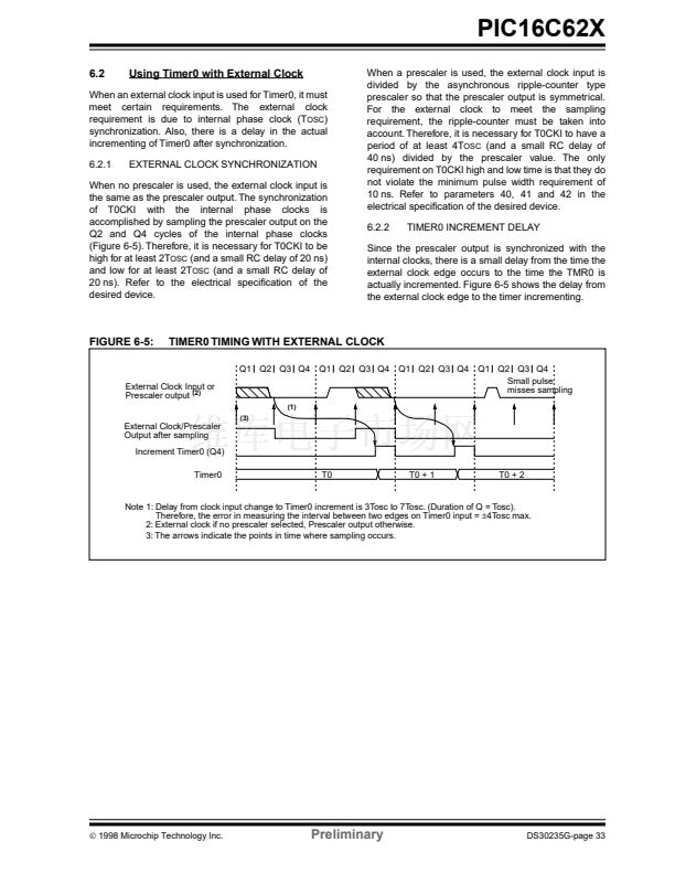
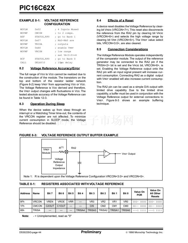
FIGURE 6-3:
PC
(Program
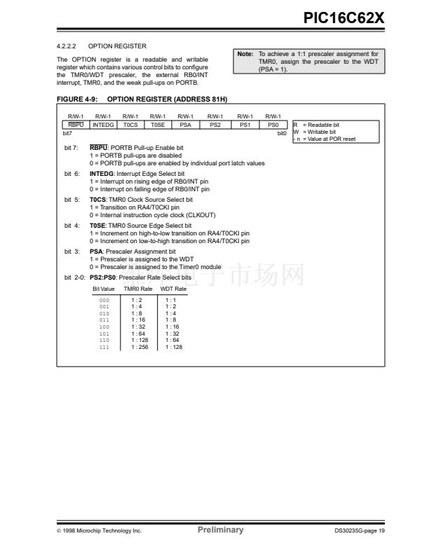
Counter)
Instruction
Fetch
TMR0
T0
TIMER0 TIMING: INTERNAL CLOCK/PRESCALE 1:2
Q1 Q2 Q3 Q4 Q1 Q2 Q3 Q4 Q1 Q2 Q3 Q4 Q1 Q2 Q3 Q4 Q1 Q2 Q3 Q4 Q1 Q2 Q3 Q4 Q1 Q2 Q3 Q4 Q1 Q2 Q3 Q4
PC-1
PC
MOVWF TMR0
PC+1
MOVF TMR0,W
PC+2
MOVF TMR0,W
PC+3
MOVF TMR0,W
PC+4
MOVF TMR0,W
PC+5
MOVF TMR0,W
PC+6
T0+1
NT0
NT0+1
Instruction
Execute
Write TMR0
executed
Read TMR0
reads NT0
Read TMR0
reads NT0
Read TMR0
reads NT0
Read TMR0
reads NT0
Read TMR0
reads NT0 + 1
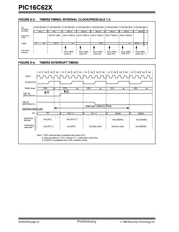
FIGURE 6-4:
TIMER0 INTERRUPT TIMING
Q1
Q2
Q3
Q4
Q1
Q2
Q3
Q4
Q1
Q2
Q3
Q4
Q1
Q2
Q3
Q4
Q1
Q2
Q3
Q4
OSC1
CLKOUT(3)
TMR0 timer
T0IF bit
(INTCON<2>)
GIE bit
(INTCON<7>)
INSTRUCTION FLOW
PC
Instruction
fetched
Instruction
executed
PC
Inst (PC)
Inst (PC-1)
PC +1
Inst (PC+1)
Dummy cycle
PC +1
0004h
Inst (0004h)
Dummy cycle
0005h
Inst (0005h)
Inst (0004h)
FEh
1
FFh
1
00h
01h
02h
Interrupt Latency Time
Inst (PC)
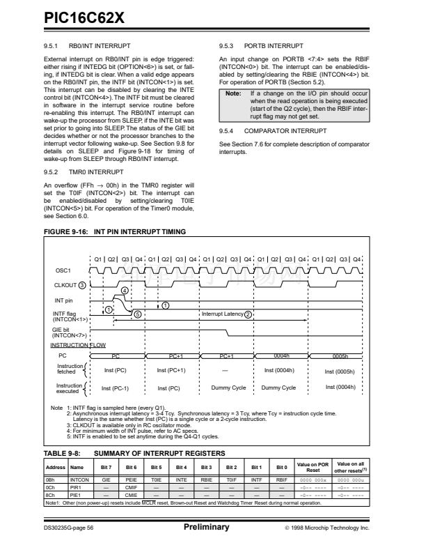
Note 1: T0IF interrupt 铿俛g is sampled here (every Q1).
2: Interrupt latency = 3T
CY
, where T
CY
= instruction cycle time.
3: CLKOUT is available only in RC oscillator mode.
DS30235G-page 32
Preliminary
漏
1998 Microchip Technology Inc.


 1
1
 2
2
 3
3
 4
4
 5
5
 6
6
 7
7
 8
8
 9
9
 10
10
 11
11
 12
12
 13
13
 14
14
 15
15
 16
16
 17
17
 18
18
 19
19
 20
20
 21
21
 22
22
 23
23
 24
24
 25
25
 26
26
 27
27
 28
28
 29
29
 30
30
 31
31
 32
32
 33
33
 34
34
 35
35
 36
36
 37
37
 38
38
 39
39
 40
40
 41
41
 42
42
 43
43
 44
44
 45
45
 46
46
 47
47
 48
48
 49
49
 50
50
 51
51
 52
52
 53
53
 54
54
 55
55
 56
56
 57
57
 58
58
 59
59
 60
60
 61
61
 62
62
 63
63
 64
64
 65
65
 66
66
 67
67
 68
68
 69
69
 70
70
 71
71
 72
72
 73
73
 74
74
 75
75
 76
76
 77
77
 78
78
 79
79
 80
80
 81
81
 82
82
 83
83
 84
84
 85
85
 86
86
 87
87
 88
88
 89
89
 90
90
 91
91
 92
92
 93
93
 94
94
 95
95
 96
96
 97
97
 98
98
 99
99
 100
100
 101
101
 102
102
 103
103
 104
104
 105
105
 106
106
 107
107
 108
108
