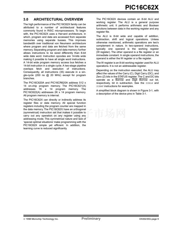
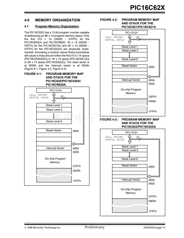
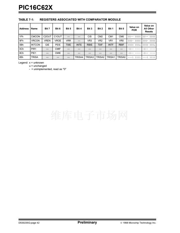
PIC16C62X
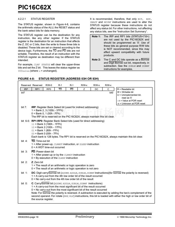
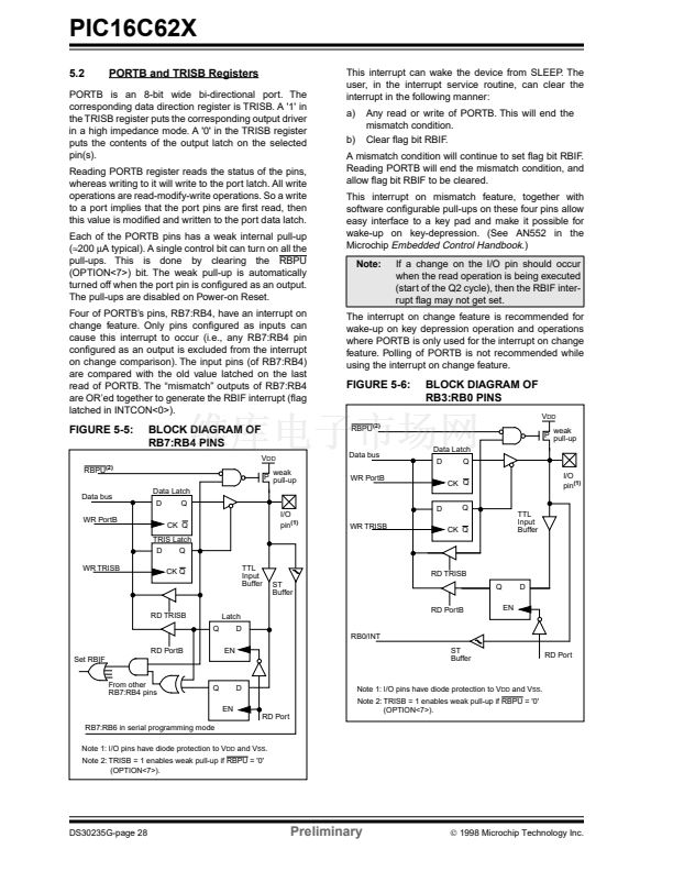
9.2.3
EXTERNAL CRYSTAL OSCILLATOR
CIRCUIT
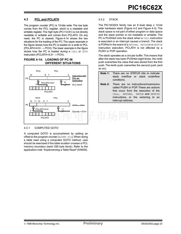
9.2.4
RC OSCILLATOR
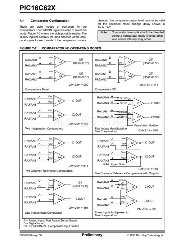
For timing insensitive applications the 鈥淩C鈥?device
option offers additional cost savings. The RC oscillator
frequency is a function of the supply voltage, the
resistor (Rext) and capacitor (Cext) values, and the
operating temperature. In addition to this, the oscillator
frequency will vary from unit to unit due to normal
process parameter variation. Furthermore, the
difference in lead frame capacitance between package
types will also affect the oscillation frequency,
especially for low Cext values. The user also needs to
take into account variation due to tolerance of external
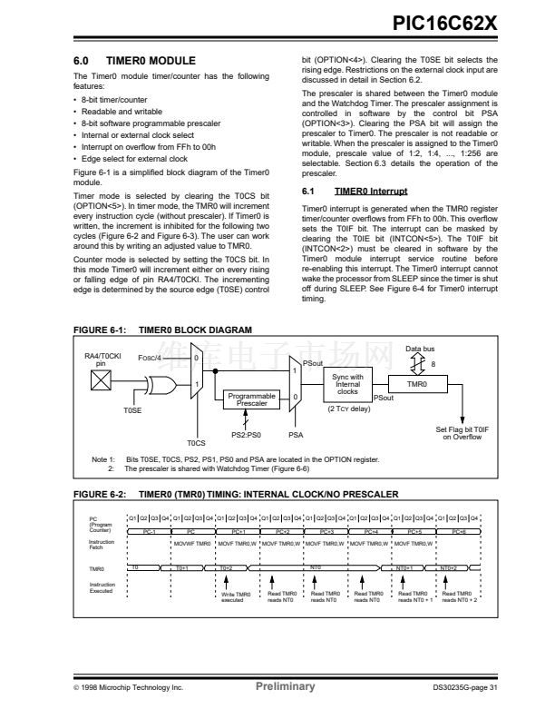
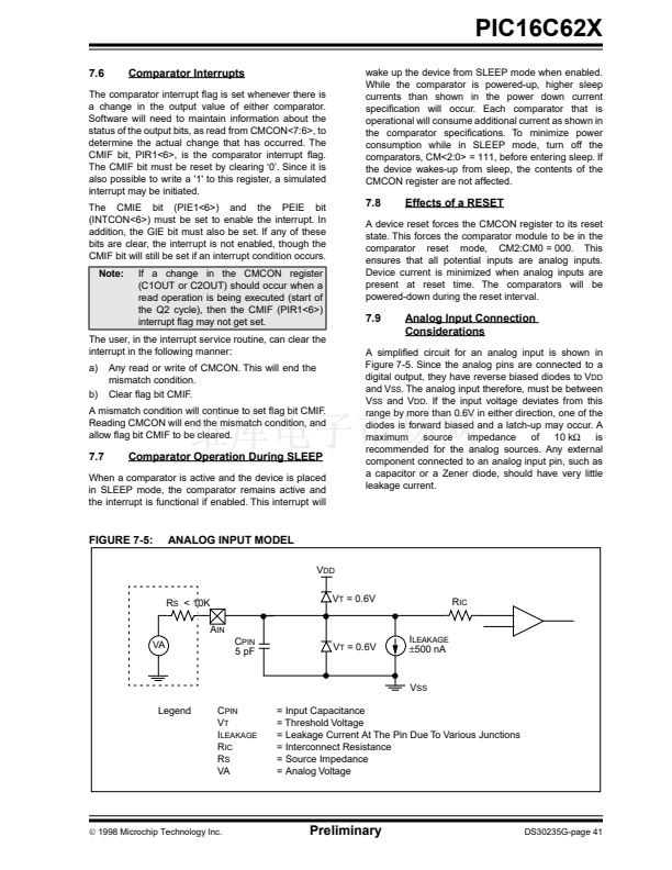
R and C components used. Figure 9-6 shows how the
R/C combination is connected to the PIC16C62X. For
Rext values below 2.2 k鈩? the oscillator operation may
become unstable, or stop completely. For very high
Rext values (e.g., 1 M鈩?, the oscillator becomes
sensitive to noise, humidity and leakage. Thus, we
recommend to keep Rext between 3 k鈩?and 100 k鈩?
Although the oscillator will operate with no external
capacitor (Cext = 0 pF), we recommend using values
above 20 pF for noise and stability reasons. With no or
small external capacitance, the oscillation frequency
can vary dramatically due to changes in external
capacitances, such as PCB trace capacitance or
package lead frame capacitance.
See Section 13.0 for RC frequency variation from part
to part due to normal process variation. The variation is
larger for larger R (since leakage current variation will
affect RC frequency more for large R) and for smaller C
(since variation of input capacitance will affect RC fre-
quency more).
See Section 13.0 for variation of oscillator frequency
due to V
DD
for given Rext/Cext values as well as
frequency variation due to operating temperature for
given R, C, and V
DD
values.
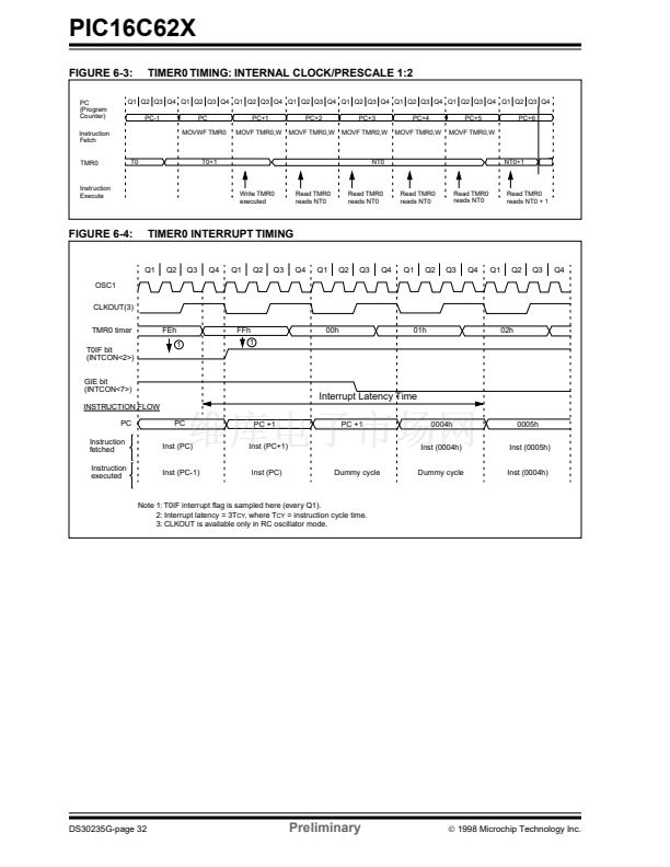
The oscillator frequency, divided by 4, is available on
the OSC2/CLKOUT pin, and can be used for test
purposes or to synchronize other logic (Figure 3-2 for
waveform).
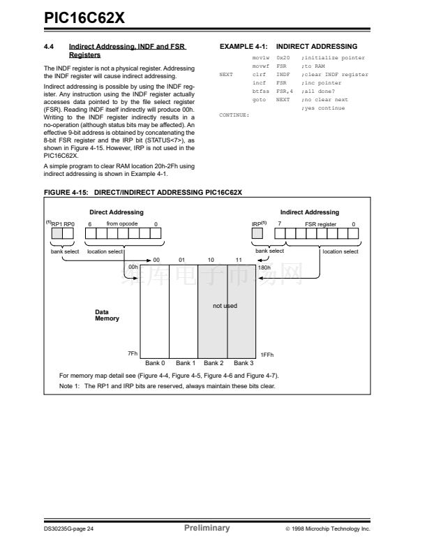
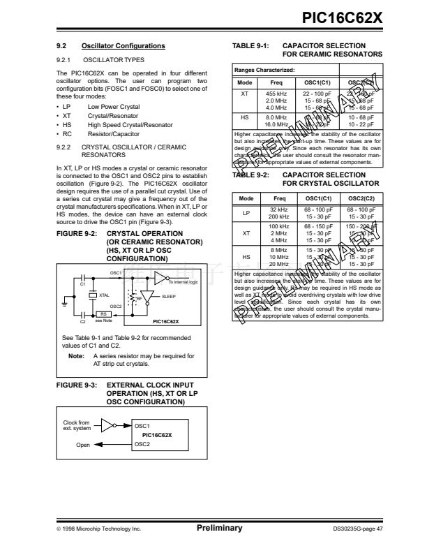
Either a prepackaged oscillator can be used or a simple
oscillator circuit with TTL gates can be built.
Prepackaged oscillators provide a wide operating
range and better stability. A well-designed crystal
oscillator will provide good performance with TTL
gates. Two types of crystal oscillator circuits can be
used; one with series resonance, or one with parallel
resonance.
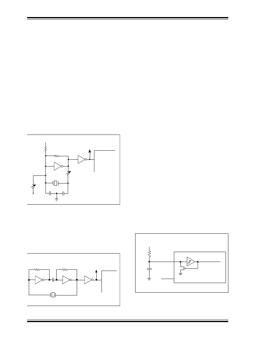
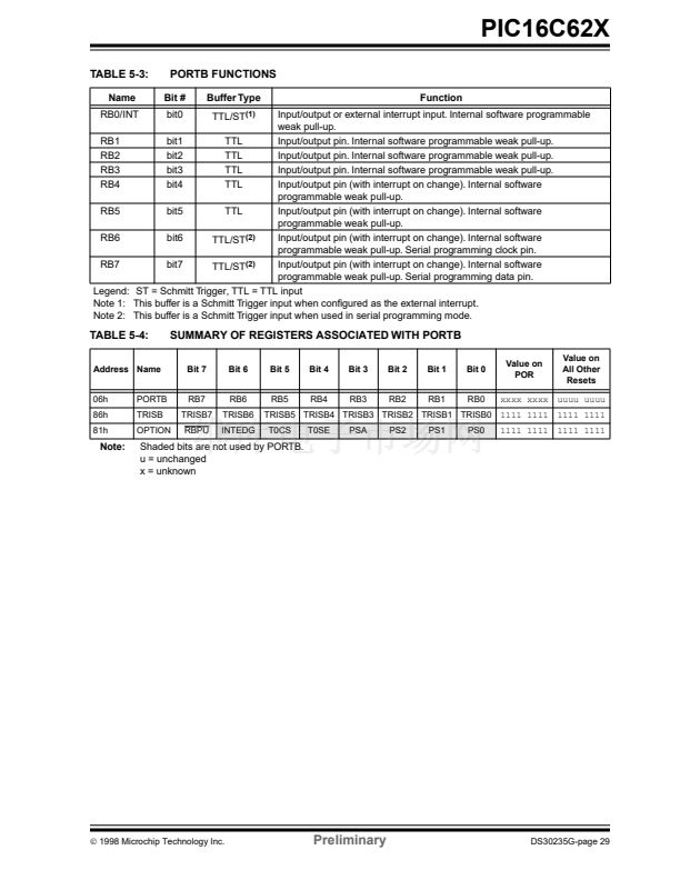
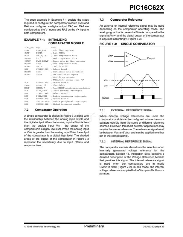
Figure 9-4 shows implementation of a parallel resonant
oscillator circuit. The circuit is designed to use the
fundamental frequency of the crystal. The 74AS04
inverter performs the 180掳 phase shift that a parallel
oscillator requires. The 4.7 k鈩?resistor provides the
negative feedback for stability. The 10 k鈩?/div>
potentiometers bias the 74AS04 in the linear region.
This could be used for external oscillator designs.
FIGURE 9-4:
EXTERNAL PARALLEL
RESONANT CRYSTAL
OSCILLATOR CIRCUIT
To other
Devices
+5V
10k
4.7k
74AS04
74AS04
PIC16C62X
CLK
IN
10k
XTAL
10k
20 pF
20 pF
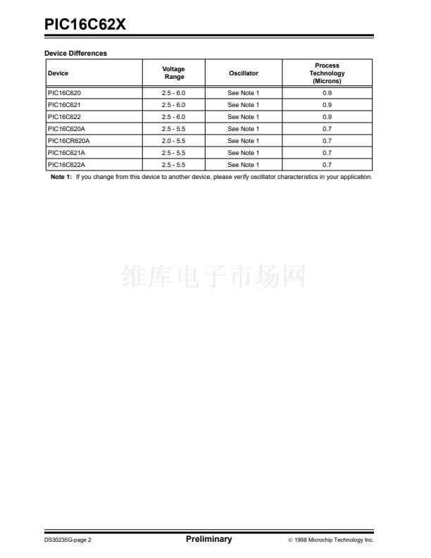
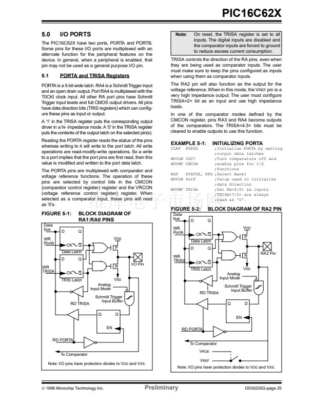
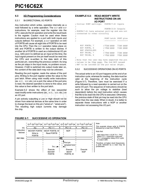
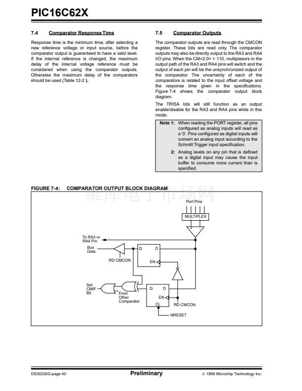
Figure 9-5 shows a series resonant oscillator circuit.
This circuit is also designed to use the fundamental
frequency of the crystal. The inverter performs a 180掳
phase shift in a series resonant oscillator circuit. The
330 k鈩?resistors provide the negative feedback to bias
the inverters in their linear region.
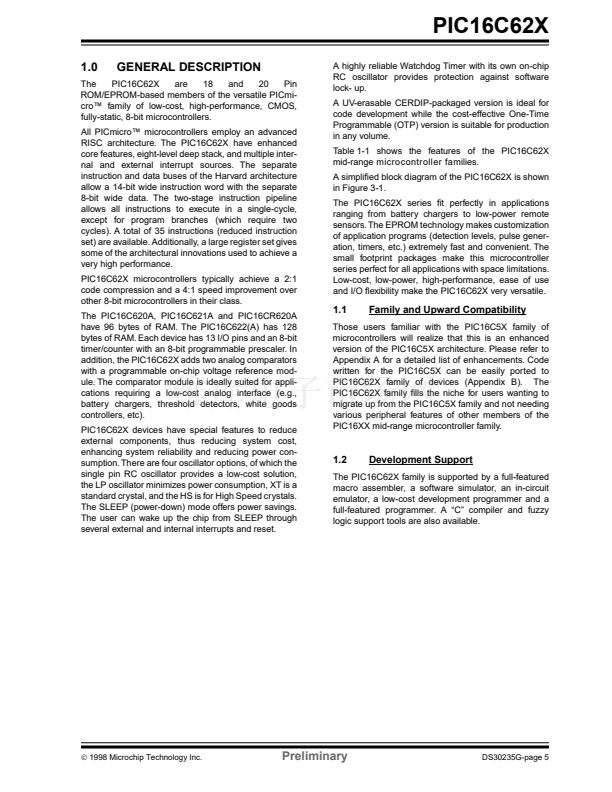
FIGURE 9-6:
V
DD
RC OSCILLATOR MODE
FIGURE 9-5:
EXTERNAL SERIES
RESONANT CRYSTAL
OSCILLATOR CIRCUIT
To other
Devices
PIC16C62X
74AS04
CLK
IN
PIC16C62X
Rext
OSC1
Internal Clock
Cext
V
DD
Fosc/4
OSC2/CLKOUT
330 k鈩?/div>
74AS04
0.1
碌F
330 k鈩?/div>
74AS04
XTAL
DS30235G-page 48
Preliminary
漏
1998 Microchip Technology Inc.


 1
1
 2
2
 3
3
 4
4
 5
5
 6
6
 7
7
 8
8
 9
9
 10
10
 11
11
 12
12
 13
13
 14
14
 15
15
 16
16
 17
17
 18
18
 19
19
 20
20
 21
21
 22
22
 23
23
 24
24
 25
25
 26
26
 27
27
 28
28
 29
29
 30
30
 31
31
 32
32
 33
33
 34
34
 35
35
 36
36
 37
37
 38
38
 39
39
 40
40
 41
41
 42
42
 43
43
 44
44
 45
45
 46
46
 47
47
 48
48
 49
49
 50
50
 51
51
 52
52
 53
53
 54
54
 55
55
 56
56
 57
57
 58
58
 59
59
 60
60
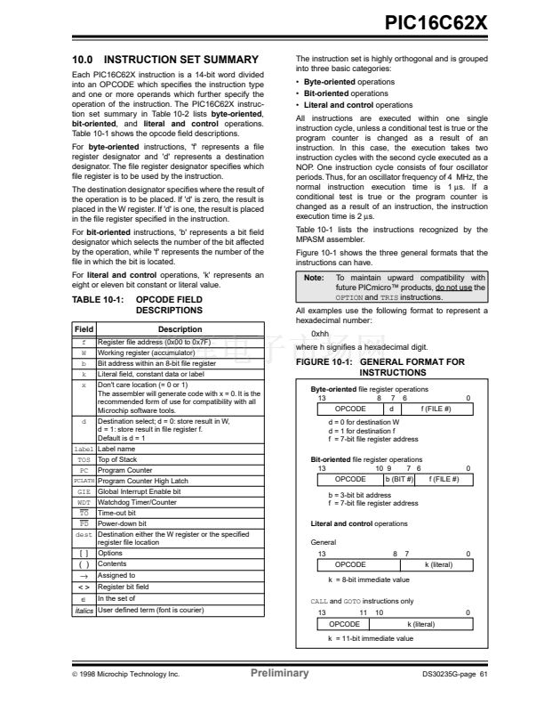 61
61
 62
62
 63
63
 64
64
 65
65
 66
66
 67
67
 68
68
 69
69
 70
70
 71
71
 72
72
 73
73
 74
74
 75
75
 76
76
 77
77
 78
78
 79
79
 80
80
 81
81
 82
82
 83
83
 84
84
 85
85
 86
86
 87
87
 88
88
 89
89
 90
90
 91
91
 92
92
 93
93
 94
94
 95
95
 96
96
 97
97
 98
98
 99
99
 100
100
 101
101
 102
102
 103
103
 104
104
 105
105
 106
106
 107
107
 108
108
