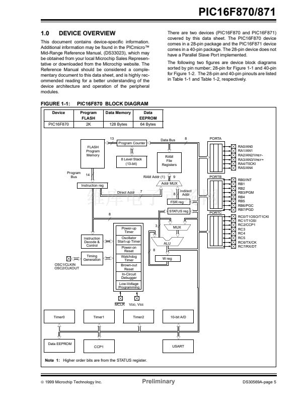
PIC16F870/871
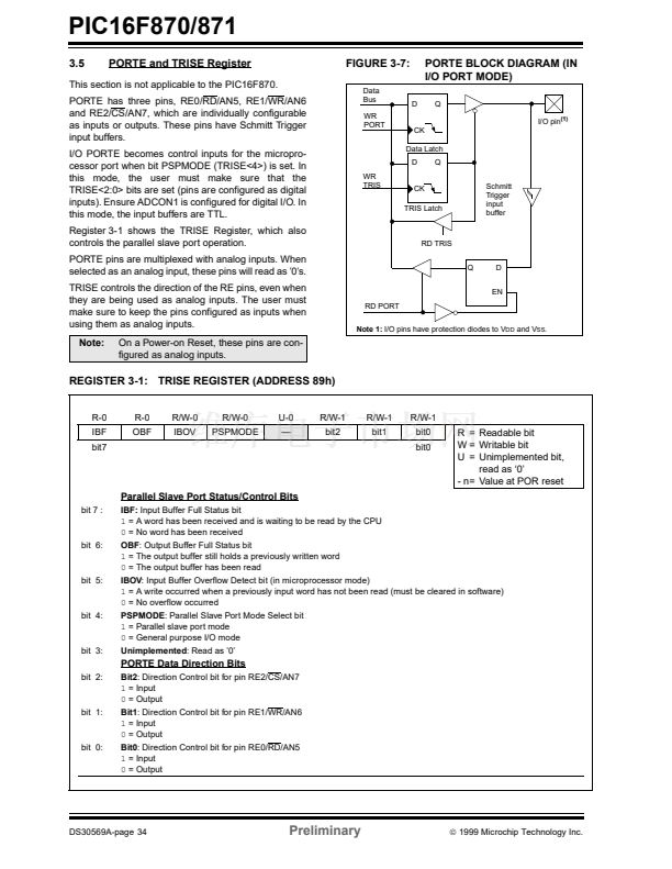
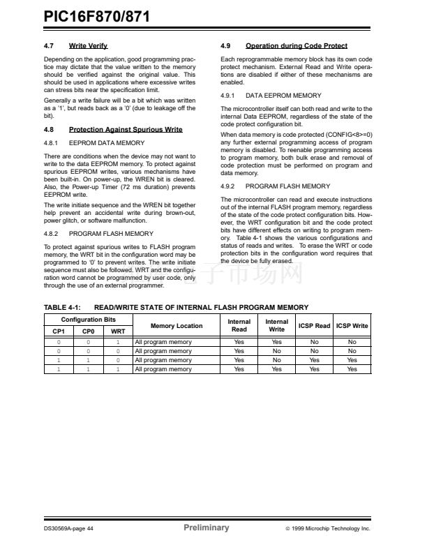
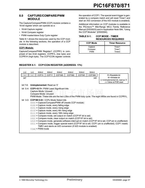
9.1
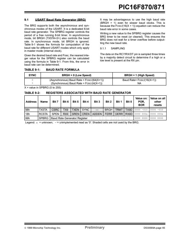
USART Baud Rate Generator (BRG)
The BRG supports both the asynchronous and syn-
chronous modes of the USART. It is a dedicated 8-bit
baud rate generator. The SPBRG register controls the
period of a free running 8-bit timer. In asynchronous
mode, bit BRGH (TXSTA<2>) also controls the baud
rate. In synchronous mode, bit BRGH is ignored.
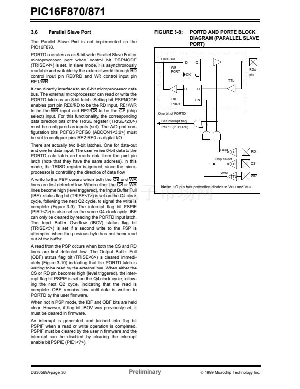
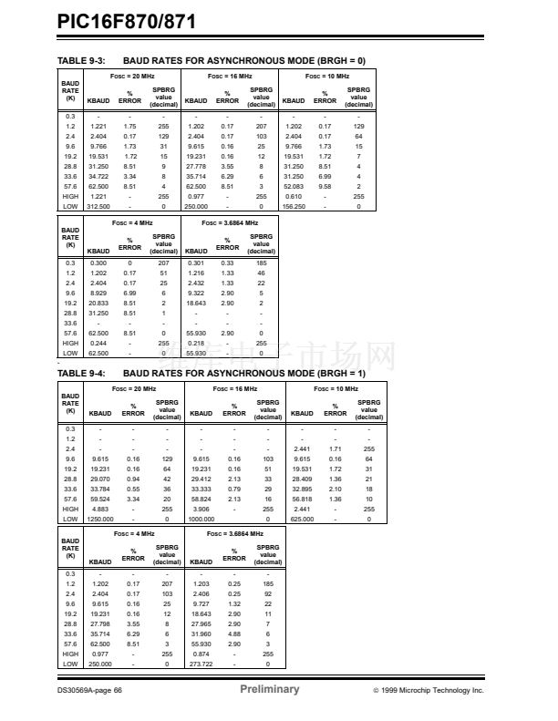
Table 9-1 shows the formula for computation of the
baud rate for different USART modes which only apply
in master mode (internal clock).
Given the desired baud rate and Fosc, the nearest inte-
ger value for the SPBRG register can be calculated
using the formula in Table 9-1. From this, the error in
baud rate can be determined.
It may be advantageous to use the high baud rate
(BRGH = 1) even for slower baud clocks. This is
because the F
OSC
/(16(X + 1)) equation can reduce the
baud rate error in some cases.
Writing a new value to the SPBRG register causes the
BRG timer to be reset (or cleared). This ensures the
BRG does not wait for a timer overflow before output-
ting the new baud rate.
9.1.1
SAMPLING
The data on the RC7/RX/DT pin is sampled three times
by a majority detect circuit to determine if a high or a
low level is present at the RX pin.
TABLE 9-1:
SYNC
0
1
BAUD RATE FORMULA
BRGH = 0 (Low Speed)
(Asynchronous) Baud Rate = F
OSC
/(64(X+1))
(Synchronous) Baud Rate = F
OSC
/(4(X+1))
BRGH = 1 (High Speed)
Baud Rate= F
OSC
/(16(X+1))
NA
X = value in SPBRG (0 to 255)
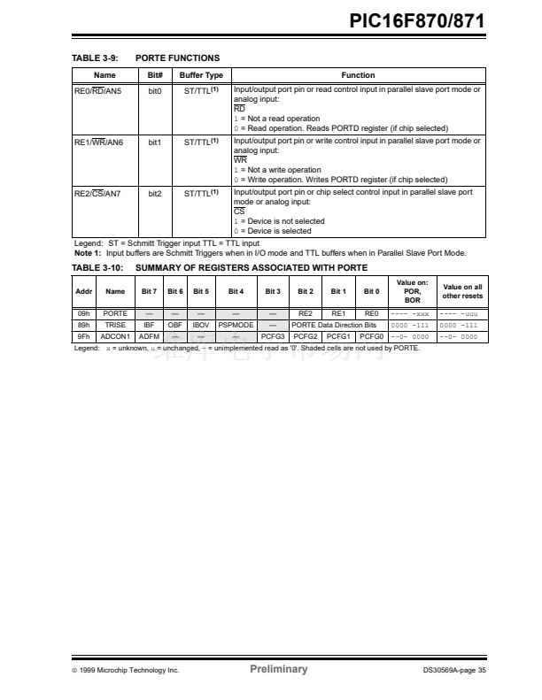
TABLE 9-2:
Address
98h
18h
99h
REGISTERS ASSOCIATED WITH BAUD RATE GENERATOR
Name
Bit 7
CSRC
SPEN
Bit 6
TX9
RX9
Bit 5
TXEN
Bit 4
SYNC
Bit 3
鈥?/div>
ADDEN
Bit 2
BRGH
FERR
Bit 1
TRMT
Bit 0
Value on:
POR,
BOR
Value on all
other
resets
TXSTA
RCSTA
TX9D
0000 -010 0000 -010
0000 0000
0000 0000
SREN CREN
OERR RX9D
0000 000x 0000 000x
SPBRG Baud Rate Generator Register
Legend:
x
= unknown,
-
= unimplemented read as '0'. Shaded cells are not used by the BRG.
漏
1999 Microchip Technology Inc.
Preliminary
DS30569A-page 65


 1
1
 2
2
 3
3
 4
4
 5
5
 6
6
 7
7
 8
8
 9
9
 10
10
 11
11
 12
12
 13
13
 14
14
 15
15
 16
16
 17
17
 18
18
 19
19
 20
20
 21
21
 22
22
 23
23
 24
24
 25
25
 26
26
 27
27
 28
28
 29
29
 30
30
 31
31
 32
32
 33
33
 34
34
 35
35
 36
36
 37
37
 38
38
 39
39
 40
40
 41
41
 42
42
 43
43
 44
44
 45
45
 46
46
 47
47
 48
48
 49
49
 50
50
 51
51
 52
52
 53
53
 54
54
 55
55
 56
56
 57
57
 58
58
 59
59
 60
60
 61
61
 62
62
 63
63
 64
64
 65
65
 66
66
 67
67
 68
68
 69
69
 70
70
 71
71
 72
72
 73
73
 74
74
 75
75
 76
76
 77
77
 78
78
 79
79
 80
80
 81
81
 82
82
 83
83
 84
84
 85
85
 86
86
 87
87
 88
88
 89
89
 90
90
 91
91
 92
92
 93
93
 94
94
 95
95
 96
96
 97
97
 98
98
 99
99
 100
100
 101
101
 102
102
 103
103
 104
104
 105
105
 106
106
 107
107
 108
108
 109
109
 110
110
 111
111
 112
112
 113
113
 114
114
 115
115
 116
116
 117
117
 118
118
 119
119
 120
120
 121
121
 122
122
 123
123
 124
124
 125
125
 126
126
 127
127
 128
128
 129
129
 130
130
 131
131
 132
132
 133
133
 134
134
 135
135
 136
136
 137
137
 138
138
 139
139
 140
140
 141
141
 142
142
 143
143
 144
144
 145
145
 146
146
 147
147
 148
148
 149
149
 150
150
 151
151
 152
152
 153
153
 154
154
 155
155
 156
156
