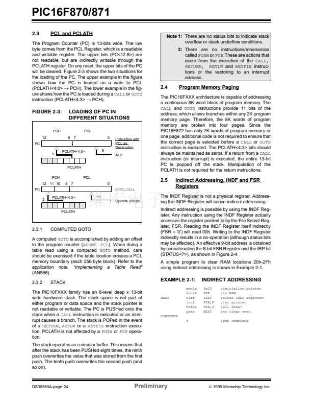
PCH). The lower example in the fig-
鈫?/div>
PCH).
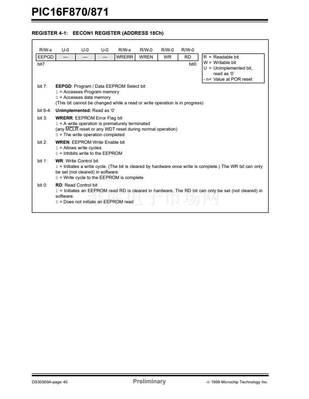
Note 1:
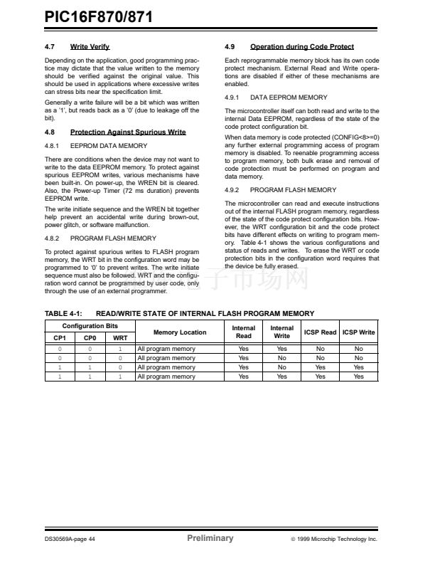
There are no status bits to indicate stack
overflow or stack underflow conditions.
2:
There are no instructions/mnemonics
called
PUSH
or
POP.
These are actions that
occur from the execution of the
CALL,
RETURN, RETLW
and
RETFIE
instruc-
tions or the vectoring to an interrupt
address.
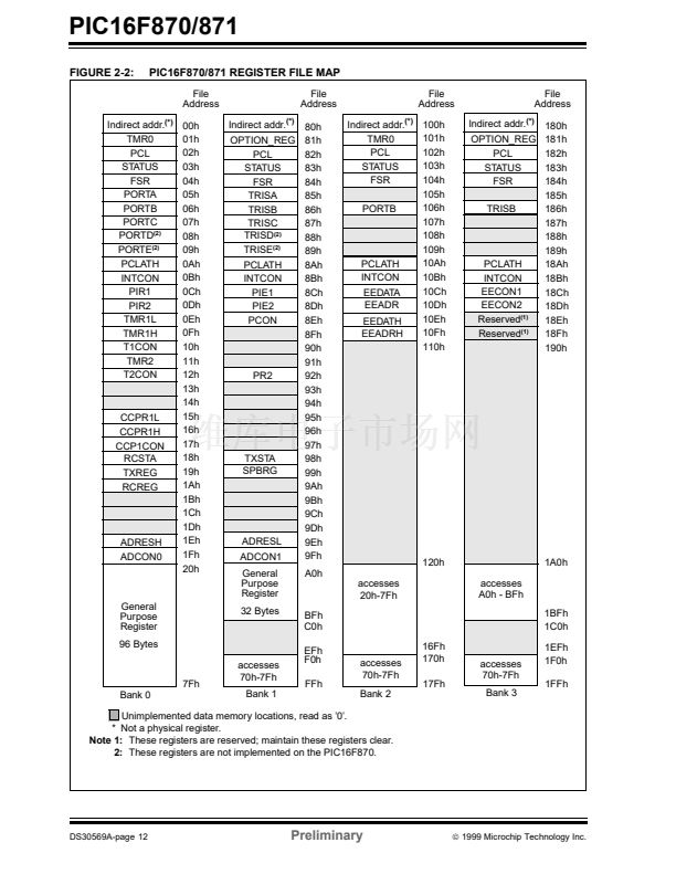
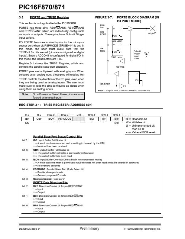
2.4
Program Memory Paging
FIGURE 2-3:
LOADING OF PC IN
DIFFERENT SITUATIONS
PCL
8
7
0
Instruction with
PCL as
Destination
ALU
PCH
12
PC
5
PCLATH<4:0>
8
PCLATH
PCH
12
PC
2
PCLATH<4:3>
11
Opcode <10:0>
PCLATH
11 10
8
7
PCL
0
GOTO,CALL
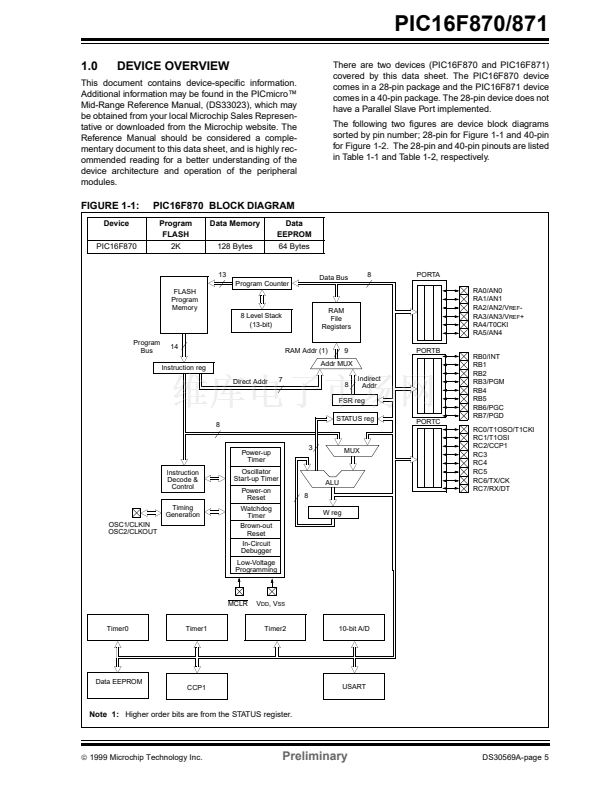
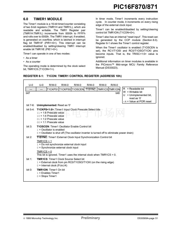
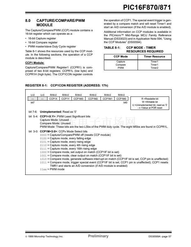
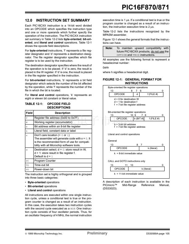
The PIC16FXXX architecture is capable of addressing
a continuous 8K word block of program memory. The
CALL
and
GOTO
instructions provide 11 bits of the
address, which allows branches within any 2K program
memory page. Therefore, the 8K words of program
memory are broken into four pages. Since the
PIC16F872 has only 2K words of program memory or
one page, additional code is not required to ensure that
the correct page is selected before a
CALL
or
GOTO
instruction is executed. The PCLATH<4:3> bits should
always be maintained as zeros. If a return from a
CALL
instruction (or interrupt) is executed, the entire 13-bit
PC is popped off the stack. Manipulation of the
PCLATH is not required for the return instructions.
2.5
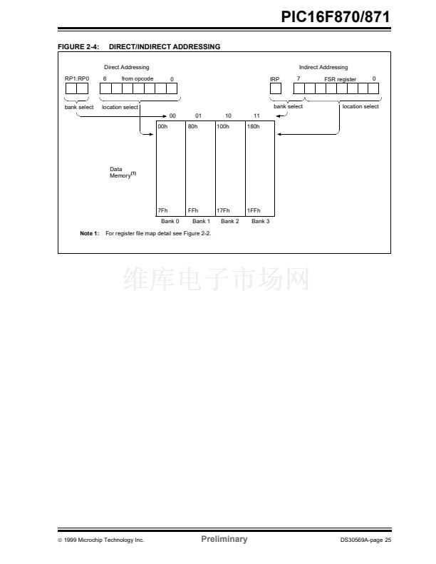
Indirect Addressing, INDF and FSR
Registers
The INDF Register is not a physical register. Address-
ing the INDF Register will cause indirect addressing.
Indirect addressing is possible by using the INDF Reg-
ister. Any instruction using the INDF Register actually
accesses the register pointed to by the File Select Reg-
ister, FSR. Reading the INDF Register itself indirectly
(FSR = 鈥?鈥? will read 00h. Writing to the INDF Register
indirectly results in a no-operation (although status bits
may be affected). An effective 9-bit address is obtained
by concatenating the 8-bit FSR Register and the IRP bit
(STATUS<7>), as shown in Figure 2-4.
A simple program to clear RAM locations 20h-2Fh
using indirect addressing is shown in Example 2-1.
2.3.1
COMPUTED GOTO
A computed
GOTO
is accomplished by adding an offset
to the program counter (ADDWF
PCL).
When doing a
table read using a computed
GOTO
method, care
should be exercised if the table location crosses a PCL
memory boundary (each 256 byte block). Refer to the
application note,
鈥淚mplementing a Table Read"
(AN556).
2.3.2
STACK
EXAMPLE 2-1:
movlw
movwf
clrf
incf
btfss
goto
:
INDIRECT ADDRESSING
0x20
FSR
INDF
FSR,F
FSR,4
NEXT
;initialize pointer
;to RAM
;clear INDF register
;inc pointer
;all done?
;no clear next
;yes continue
The PIC16FXXX family has an 8-level deep x 13-bit
wide hardware stack. The stack space is not part of
either program or data space and the stack pointer is
not readable or writable. The PC is PUSHed onto the
stack when a
CALL
instruction is executed or an inter-
rupt causes a branch. The stack is POPed in the event
of a
RETURN,RETLW
or a
RETFIE
instruction execu-
tion. PCLATH is not affected by a
PUSH
or
POP
opera-
tion.
The stack operates as a circular buffer. This means that
after the stack has been PUSHed eight times, the ninth
push overwrites the value that was stored from the first
push. The tenth push overwrites the second push (and
so on).
NEXT
CONTINUE
DS30569A-page 24
Preliminary
漏
1999 Microchip Technology Inc.


 1
1
 2
2
 3
3
 4
4
 5
5
 6
6
 7
7
 8
8
 9
9
 10
10
 11
11
 12
12
 13
13
 14
14
 15
15
 16
16
 17
17
 18
18
 19
19
 20
20
 21
21
 22
22
 23
23
 24
24
 25
25
 26
26
 27
27
 28
28
 29
29
 30
30
 31
31
 32
32
 33
33
 34
34
 35
35
 36
36
 37
37
 38
38
 39
39
 40
40
 41
41
 42
42
 43
43
 44
44
 45
45
 46
46
 47
47
 48
48
 49
49
 50
50
 51
51
 52
52
 53
53
 54
54
 55
55
 56
56
 57
57
 58
58
 59
59
 60
60
 61
61
 62
62
 63
63
 64
64
 65
65
 66
66
 67
67
 68
68
 69
69
 70
70
 71
71
 72
72
 73
73
 74
74
 75
75
 76
76
 77
77
 78
78
 79
79
 80
80
 81
81
 82
82
 83
83
 84
84
 85
85
 86
86
 87
87
 88
88
 89
89
 90
90
 91
91
 92
92
 93
93
 94
94
 95
95
 96
96
 97
97
 98
98
 99
99
 100
100
 101
101
 102
102
 103
103
 104
104
 105
105
 106
106
 107
107
 108
108
 109
109
 110
110
 111
111
 112
112
 113
113
 114
114
 115
115
 116
116
 117
117
 118
118
 119
119
 120
120
 121
121
 122
122
 123
123
 124
124
 125
125
 126
126
 127
127
 128
128
 129
129
 130
130
 131
131
 132
132
 133
133
 134
134
 135
135
 136
136
 137
137
 138
138
 139
139
 140
140
 141
141
 142
142
 143
143
 144
144
 145
145
 146
146
 147
147
 148
148
 149
149
 150
150
 151
151
 152
152
 153
153
 154
154
 155
155
 156
156
