Geode鈩?CS5530
Functional Description
(Continued)
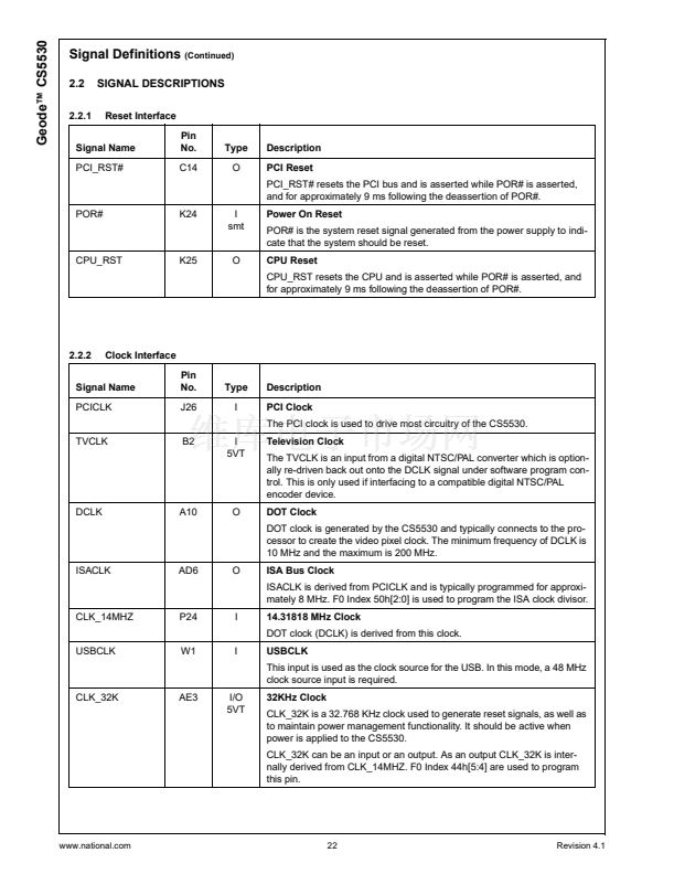
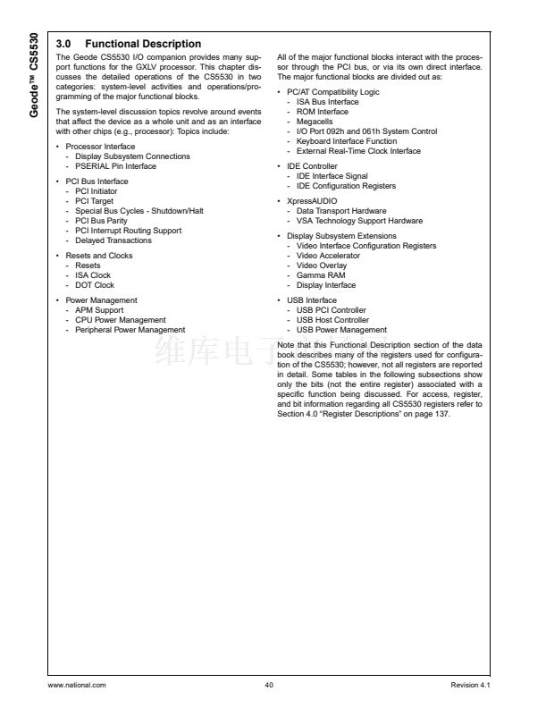
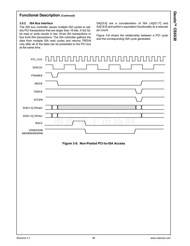
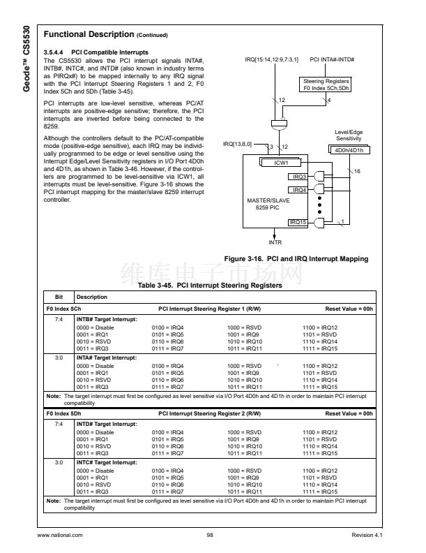
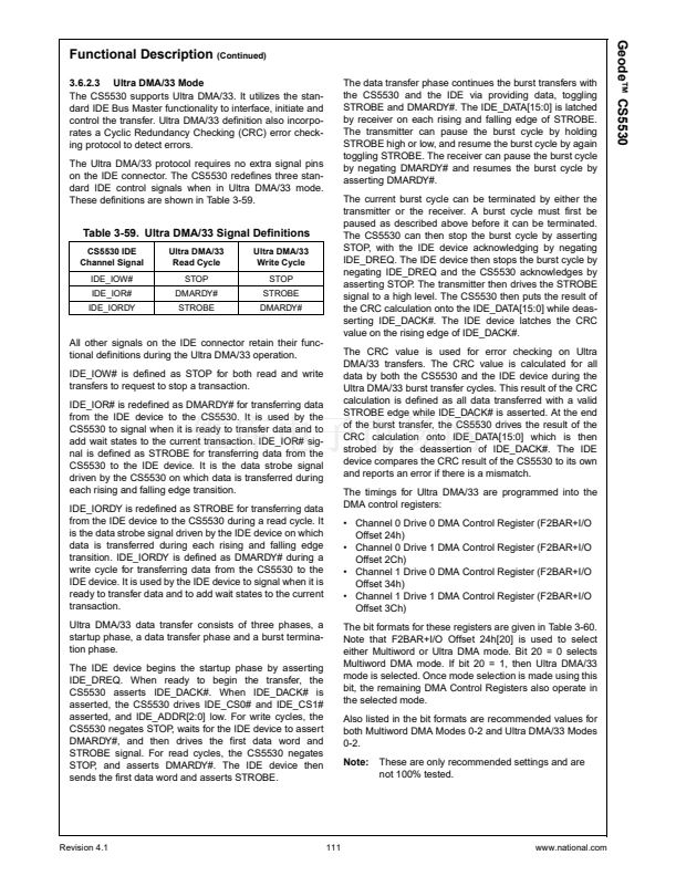
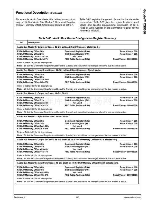
3.2.3 Special Bus Cycles鈥揝hutdown/Halt
The PCI interface does not pass Special Bus Cycles to
the ISA interface, since special cycles by definition have
no destination. However, the PCI interface monitors the
PCI bus for Shutdown and Halt Special Bus Cycles.
Upon detection of a Shutdown Special Bus Cycle, a
WM_RST SMI is generated after a delay of three PCI
clock cycles. PCI Shutdown Special Cycles are detected
when C/BE[3:0]# = 0001 during the address phase and
AD[31:0] = xxxx0000h during the data phase. C/BE[3:0]#
are also properly asserted during the data phase.
Upon detection of a Halt Special Bus Cycle, the CS5530
completes the cycle by asserting TRDY#. PCI Halt Spe-
cial Bus Cycles are detected when CBE[3:0]# = 0001 dur-
ing the address phase and AD[31:0] = xxxx0001h during
the data phase of a Halt cycle. CBE[3:0]# are also prop-
erly asserted during the data phase.
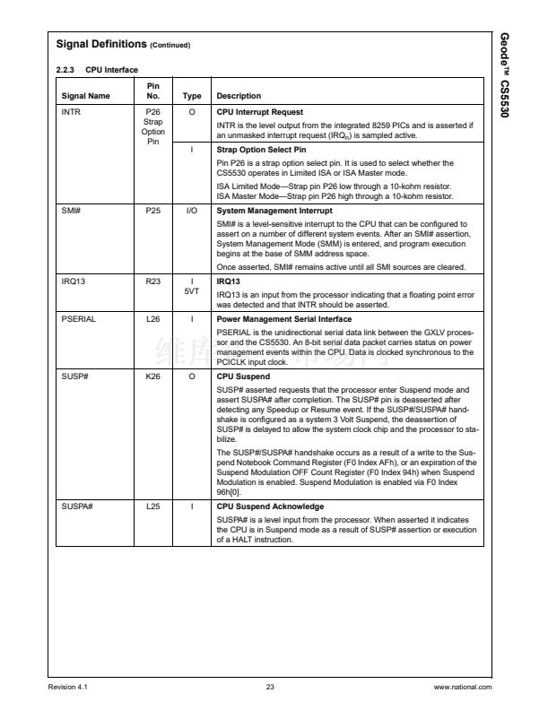
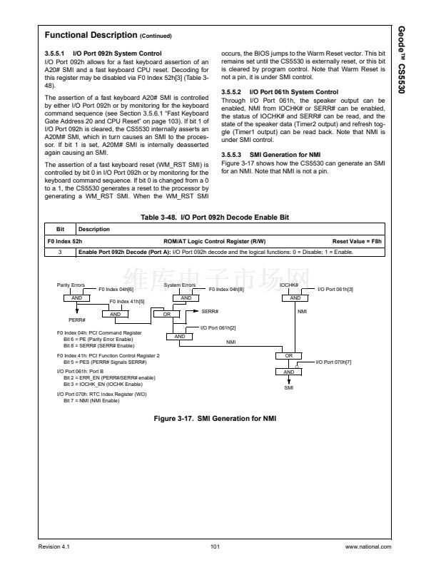
3.2.4 PCI Bus Parity
When the CS5530 is the PCI initiator, it generates
address parity for read and write cycles. It checks data
parity for read cycles and it generates data parity for write
cycles. The PAR signal is an even-parity bit that is calcu-
lated across 36 bits of AD[31:0] plus C/BE[3:0]#.
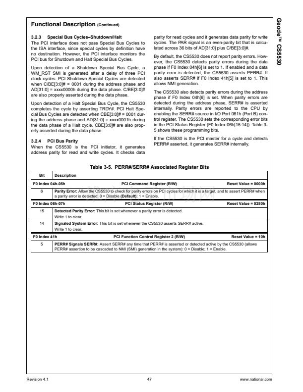
By default, the CS5530 does not report parity errors. How-
ever, the CS5530 detects parity errors during the data
phase if F0 Index 04h[6] is set to 1. If enabled and a data
parity error is detected, the CS5530 asserts PERR#. It
also asserts SERR# if F0 Index 41h[5] is set to 1. This
allows NMI generation.
The CS5530 also detects parity errors during the address
phase if F0 Index 04h[6] is set. When parity errors are
detected during the address phase, SERR# is asserted
internally. Parity errors are reported to the CPU by
enabling the SERR# source in I/O Port 061h (Port B) con-
trol register. The CS5530 sets the corresponding error bits
in the PCI Status Register (F0 Index 06h[15:14]). Table 3-
5 shows these programming bits.
If the CS5530 is the PCI master for a cycle and detects
PERR# asserted, it generates SERR# internally.
Table 3-5. PERR#/SERR# Associated Register Bits
Bit
Description
PCI Command Register (R/W)
Reset Value = 0000h
F0 Index 04h-05h
6
Parity Error:
Allow the CS5530 to check for parity errors on PCI cycles for which it is a target, and to assert PERR# when
a parity error is detected: 0 = Disable
(Default);
1 = Enable.
PCI Status Register (R/W)
Reset Value = 0280h
F0 Index 06h-07h
15
14
Write 1 to clear.
Detected Parity Error:
This bit is set whenever a parity error is detected.
Signaled System Error:
This bit is set whenever the CS5530 asserts SERR# active.
Write 1 to clear.
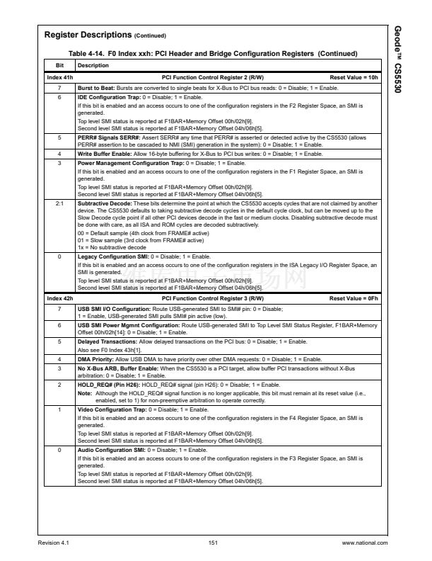
PCI Function Control Register 2 (R/W)
Reset Value = 10h
F0 Index 41h
5
PERR# Signals SERR#:
Assert SERR# any time that PERR# is asserted or detected active by the CS5530 (allows
PERR# assertion to be cascaded to NMI (SMI) generation in the system): 0 = Disable; 1 = Enable.
Revision 4.1
47
www.national.com


 1
1
 2
2
 3
3
 4
4
 5
5
 6
6
 7
7
 8
8
 9
9
 10
10
 11
11
 12
12
 13
13
 14
14
 15
15
 16
16
 17
17
 18
18
 19
19
 20
20
 21
21
 22
22
 23
23
 24
24
 25
25
 26
26
 27
27
 28
28
 29
29
 30
30
 31
31
 32
32
 33
33
 34
34
 35
35
 36
36
 37
37
 38
38
 39
39
 40
40
 41
41
 42
42
 43
43
 44
44
 45
45
 46
46
 47
47
 48
48
 49
49
 50
50
 51
51
 52
52
 53
53
 54
54
 55
55
 56
56
 57
57
 58
58
 59
59
 60
60
 61
61
 62
62
 63
63
 64
64
 65
65
 66
66
 67
67
 68
68
 69
69
 70
70
 71
71
 72
72
 73
73
 74
74
 75
75
 76
76
 77
77
 78
78
 79
79
 80
80
 81
81
 82
82
 83
83
 84
84
 85
85
 86
86
 87
87
 88
88
 89
89
 90
90
 91
91
 92
92
 93
93
 94
94
 95
95
 96
96
 97
97
 98
98
 99
99
 100
100
 101
101
 102
102
 103
103
 104
104
 105
105
 106
106
 107
107
 108
108
 109
109
 110
110
 111
111
 112
112
 113
113
 114
114
 115
115
 116
116
 117
117
 118
118
 119
119
 120
120
 121
121
 122
122
 123
123
 124
124
 125
125
 126
126
 127
127
 128
128
 129
129
 130
130
 131
131
 132
132
 133
133
 134
134
 135
135
 136
136
 137
137
 138
138
 139
139
 140
140
 141
141
 142
142
 143
143
 144
144
 145
145
 146
146
 147
147
 148
148
 149
149
 150
150
 151
151
 152
152
 153
153
 154
154
 155
155
 156
156
 157
157
 158
158
 159
159
 160
160
 161
161
 162
162
 163
163
 164
164
 165
165
 166
166
 167
167
 168
168
 169
169
 170
170
 171
171
 172
172
 173
173
 174
174
 175
175
 176
176
 177
177
 178
178
 179
179
 180
180
 181
181
 182
182
 183
183
 184
184
 185
185
 186
186
 187
187
 188
188
 189
189
 190
190
 191
191
 192
192
 193
193
 194
194
 195
195
 196
196
 197
197
 198
198
 199
199
 200
200
 201
201
 202
202
 203
203
 204
204
 205
205
 206
206
 207
207
 208
208
 209
209
 210
210
 211
211
 212
212
 213
213
 214
214
 215
215
 216
216
 217
217
 218
218
 219
219
 220
220
 221
221
 222
222
 223
223
 224
224
 225
225
 226
226
 227
227
 228
228
 229
229
 230
230
 231
231
 232
232
 233
233
 234
234
 235
235
 236
236
 237
237
 238
238
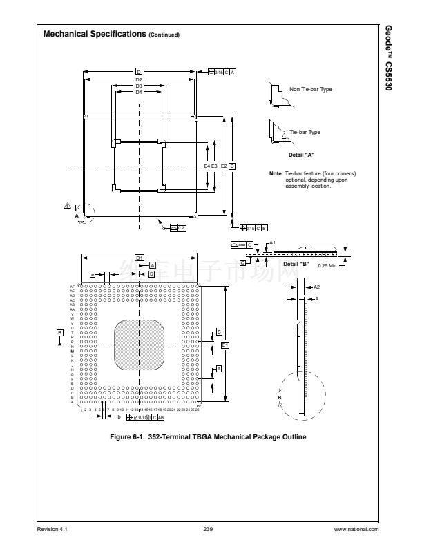 239
239
 240
240
 241
241
