Geode鈩?CS5530
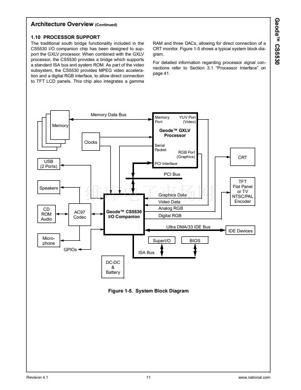
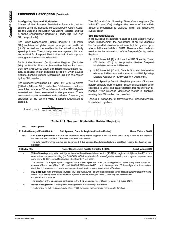
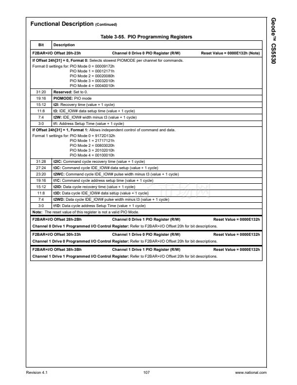
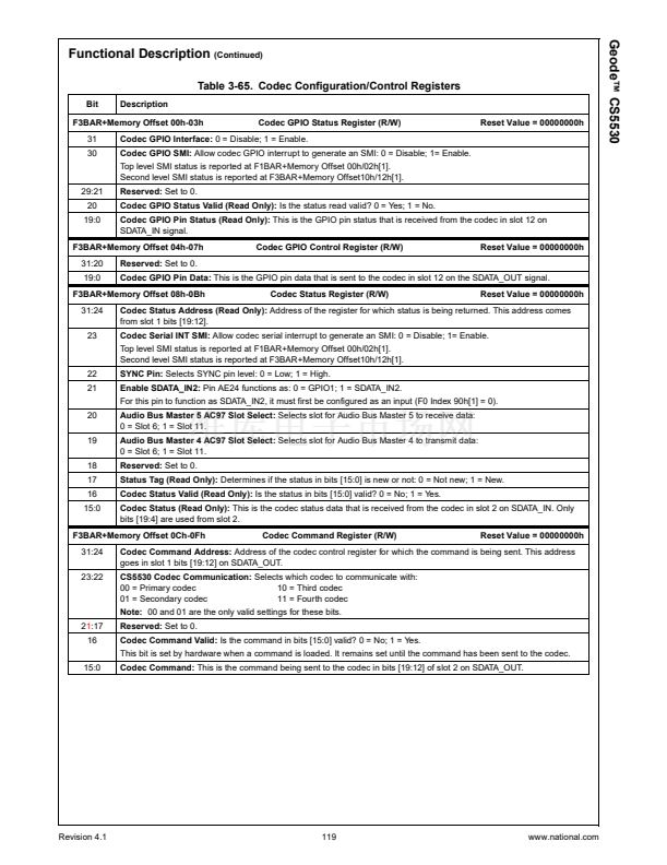
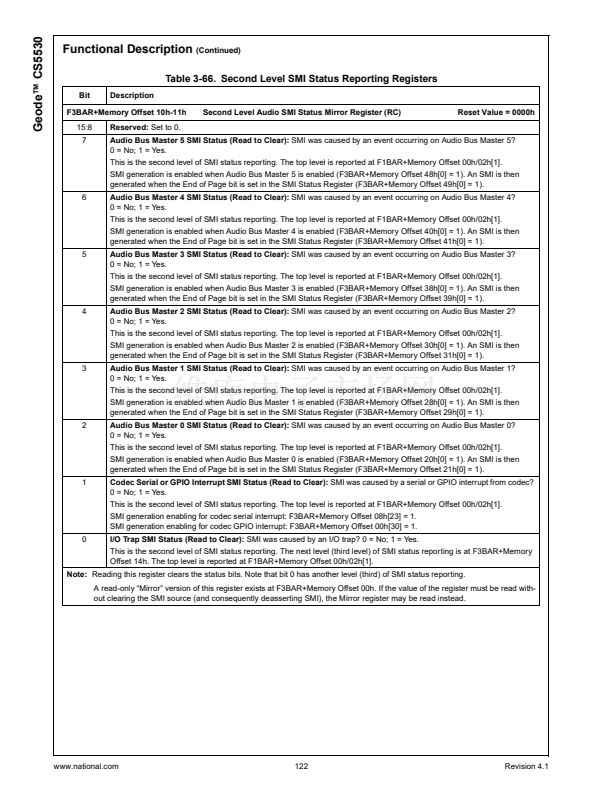
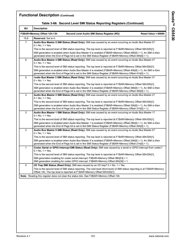
Functional Description
(Continued)
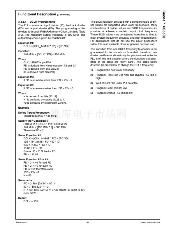
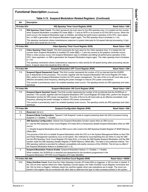
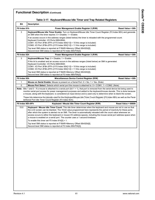
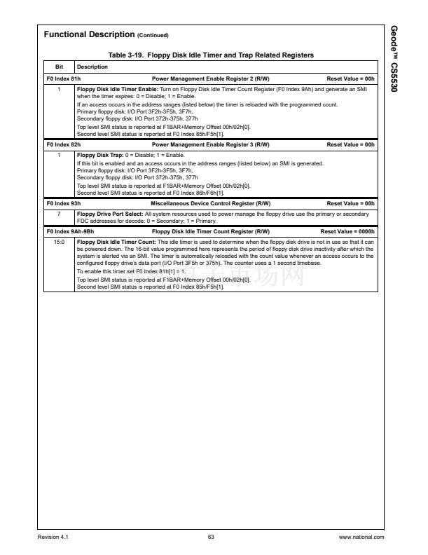
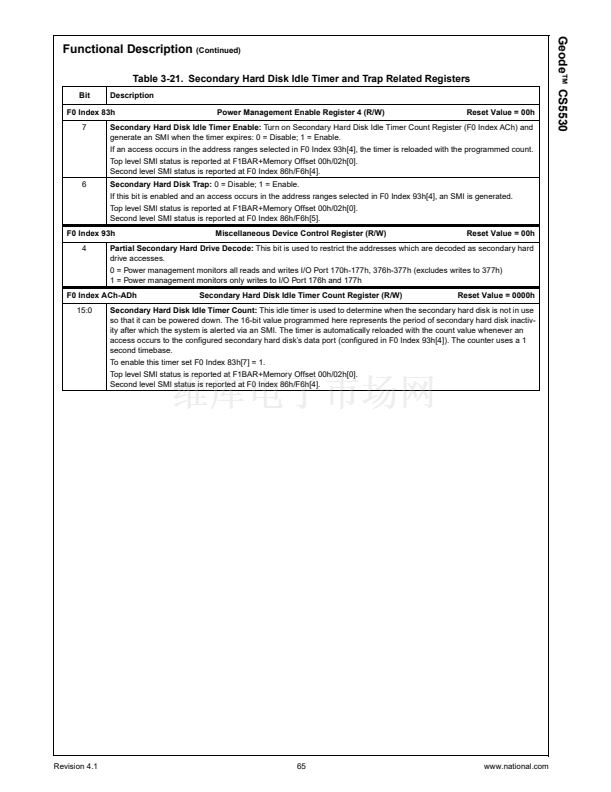
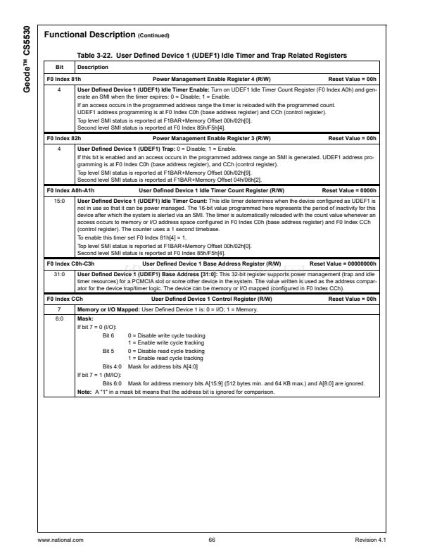
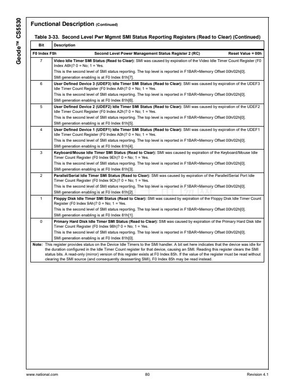
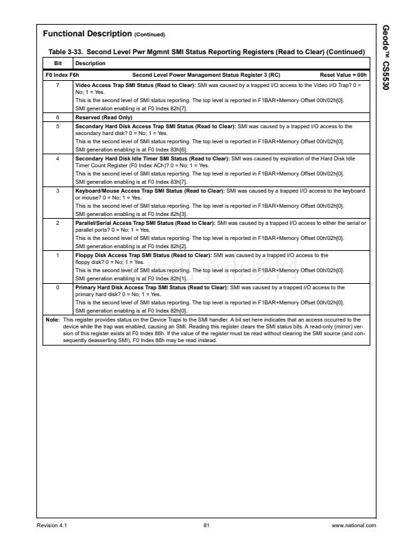
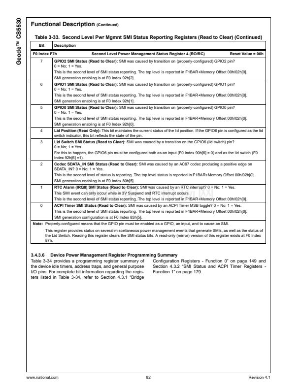
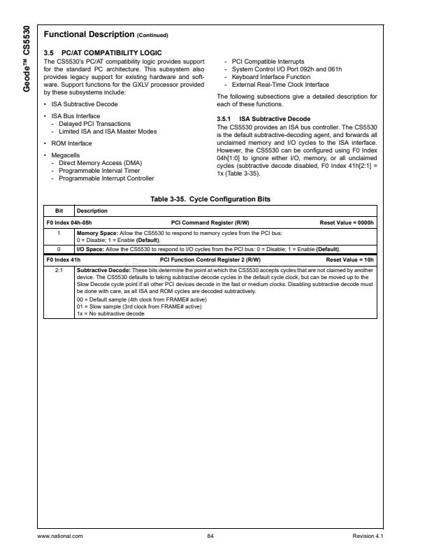
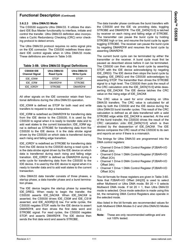
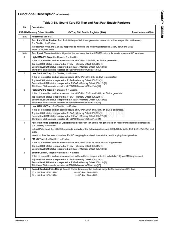
Table 3-13. Suspend Modulation Related Registers (Continued)
Bit
Description
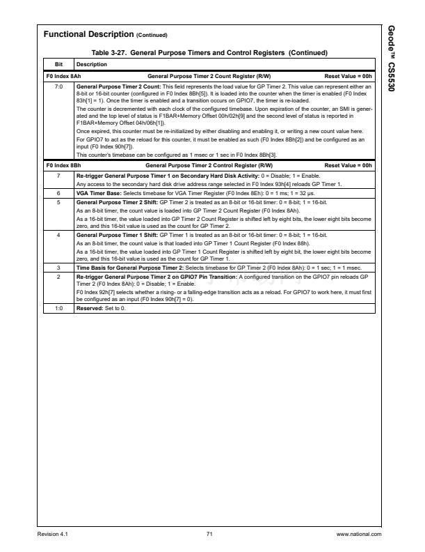
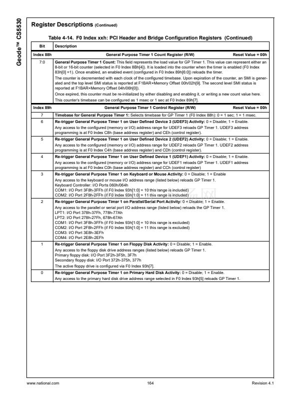
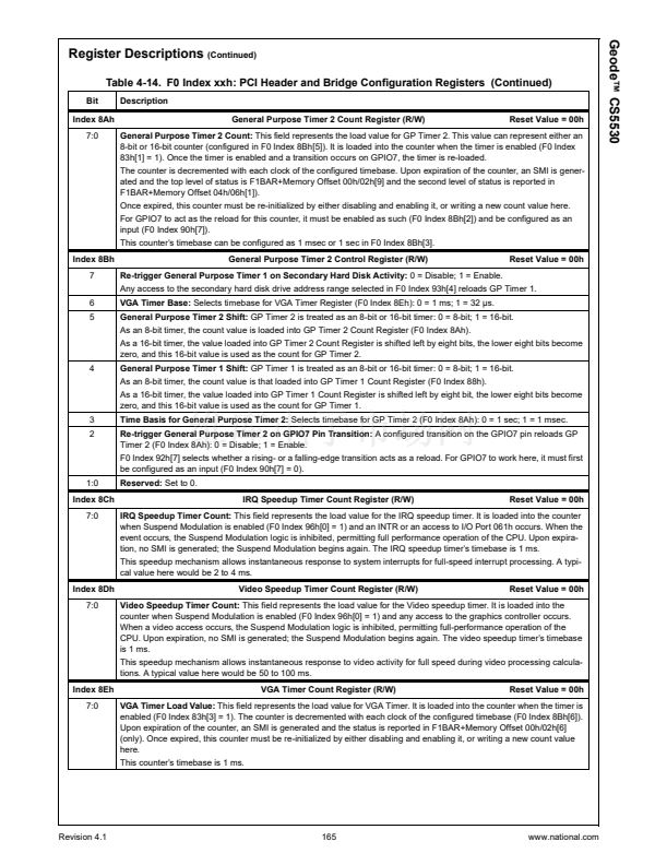
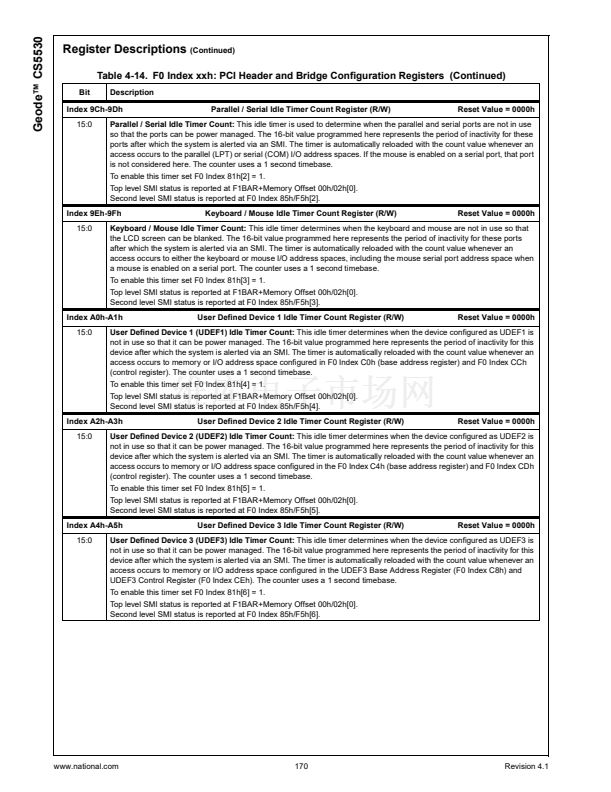
IRQ Speedup Timer Count Register (R/W)
Reset Value = 00h
F0 Index 8Ch
7:0
IRQ Speedup Timer Count:
This field represents the load value for the IRQ speedup timer. It is loaded into the counter
when Suspend Modulation is enabled (F0 Index 96[0] = 1) and an INTR or an access to I/O Port 061h occurs. When the
event occurs, the Suspend Modulation logic is inhibited, permitting full performance operation of the CPU. Upon expira-
tion, no SMI is generated; the Suspend Modulation begins again. The IRQ speedup timer鈥檚 timebase is 1 ms.
This speedup mechanism allows instantaneous response to system interrupts for full-speed interrupt processing. A typi-
cal value here would be 2 to 4 ms.
F0 Index 8Dh
7:0
Video Speedup Timer Count Register (R/W)
Reset Value = 00h
Video Speedup Timer Count:
This field represents the load value for the Video speedup timer. It is loaded into the
counter when Suspend Modulation is enabled (F0 Index 96[0] = 1) and any access to the graphics controller occurs.
When a video access occurs, the Suspend Modulation logic is inhibited, permitting full-performance operation of the
CPU. Upon expiration, no SMI is generated; the Suspend Modulation begins again. The video speedup timer鈥檚 timebase
is 1 ms.
This speedup mechanism allows instantaneous response to video activity for full speed during video processing calcula-
tions. A typical value here would be 50 to 100 ms.
F0 Index 94h
7:0
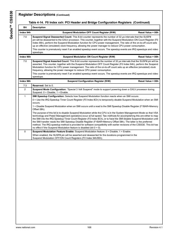
Suspend Modulation OFF Count Register (R/W)
Reset Value = 00h
Suspend Signal Deasserted Count:
This 8-bit counter represents the number of 32 碌s intervals that the SUSP#
pin is deasserted to the processor. This counter, together with the Suspend Modulation ON Count Register (F0 Index
95h), perform the Suspend Modulation function for CPU power management. The ratio of the on-to-off count sets up an
effective (emulated) clock frequency, allowing the power manager to reduce CPU power consumption.
This counter is prematurely reset if an enabled speedup event occurs. The speedup events are IRQ speedups and video
speedups.
F0 Index 95h
7:0
Suspend Modulation ON Count Register (R/W)
Reset Value = 00h
Suspend Signal Asserted Count:
This 8-bit counter represents the number of 32 碌s intervals that the SUSP# pin is
asserted. This counter, together with the Suspend Modulation OFF Count Register (F0 Index 94h), perform the Suspend
Modulation function for CPU power management. The ratio of the on-to-off count sets up an effective (emulated) clock
frequency, allowing the power manager to reduce CPU power consumption.
This counter is prematurely reset if an enabled speedup event occurs. The speedup events are IRQ speedups and video
speedups.
F0 Index 96h
7:3
2
1
Reserved:
Set to 0.
Suspend Configuration Register (R/W)
Reset Value = 00h
Suspend Mode Configuration:
鈥淪pecial 3 Volt Suspend鈥?mode to support powering down the GXLV processor during
Suspend: 0 = Disable; 1 = Enable.
SMI Speedup Configuration:
Selects how Suspend Modulation function reacts when an SMI occurs:
0 = Use the IRQ Speedup Timer Count Register (F0 Index 8Ch) to temporarily disable Suspend Modulation when an SMI
occurs.
1 = Disable Suspend Modulation when an SMI occurs until a read to the SMI Speedup Disable Register (F1BAR+Memory
Offset 08h).
The purpose of this bit is to disable Suspend Modulation while the CPU is in the System Management Mode so that VSA
and Power Management operations occur at full speed. Two methods for accomplishing this are either to map the SMI
into the IRQ Speedup Timer Count Register (F0 Index 8Ch), or to have the SMI disable Suspend Modulation until the SMI
handler reads the SMI Speedup Disable Register (F1BAR+Memory Offset 08h). The latter is the preferred method. The
IRQ speedup method is provided for software compatibility with earlier revisions of the CS5530. This bit has no effect if
the Suspend Modulation feature is disabled (bit 0 = 0).
0
Suspend Modulation Feature Enable:
Suspend Modulation feature: 0 = Disable; 1 = Enable.
When enabled, the SUSP# pin is asserted and deasserted for the durations programmed in the
Suspend Modulation OFF/ON Count Registers (F0 Index 94h/95h).
F0 Index A8h-A9h
15:0
Video Overflow Count Register (R/W)
Reset Value = 0000h
Video Overflow Count:
Each time the Video Speedup Counter (F0 Index 8Dh) is triggered, a 100 ms timer is started. If
the 100 ms timer expires before the Video Speedup Counter lapses, the Video Overflow Count Register increments and
the 100 ms timer re-triggers. Software clears the overflow register when new evaluations are to begin. The count con-
tained in this register may be combined with other data to determine the type of video accesses present in the system.
Revision 4.1
57
www.national.com


 1
1
 2
2
 3
3
 4
4
 5
5
 6
6
 7
7
 8
8
 9
9
 10
10
 11
11
 12
12
 13
13
 14
14
 15
15
 16
16
 17
17
 18
18
 19
19
 20
20
 21
21
 22
22
 23
23
 24
24
 25
25
 26
26
 27
27
 28
28
 29
29
 30
30
 31
31
 32
32
 33
33
 34
34
 35
35
 36
36
 37
37
 38
38
 39
39
 40
40
 41
41
 42
42
 43
43
 44
44
 45
45
 46
46
 47
47
 48
48
 49
49
 50
50
 51
51
 52
52
 53
53
 54
54
 55
55
 56
56
 57
57
 58
58
 59
59
 60
60
 61
61
 62
62
 63
63
 64
64
 65
65
 66
66
 67
67
 68
68
 69
69
 70
70
 71
71
 72
72
 73
73
 74
74
 75
75
 76
76
 77
77
 78
78
 79
79
 80
80
 81
81
 82
82
 83
83
 84
84
 85
85
 86
86
 87
87
 88
88
 89
89
 90
90
 91
91
 92
92
 93
93
 94
94
 95
95
 96
96
 97
97
 98
98
 99
99
 100
100
 101
101
 102
102
 103
103
 104
104
 105
105
 106
106
 107
107
 108
108
 109
109
 110
110
 111
111
 112
112
 113
113
 114
114
 115
115
 116
116
 117
117
 118
118
 119
119
 120
120
 121
121
 122
122
 123
123
 124
124
 125
125
 126
126
 127
127
 128
128
 129
129
 130
130
 131
131
 132
132
 133
133
 134
134
 135
135
 136
136
 137
137
 138
138
 139
139
 140
140
 141
141
 142
142
 143
143
 144
144
 145
145
 146
146
 147
147
 148
148
 149
149
 150
150
 151
151
 152
152
 153
153
 154
154
 155
155
 156
156
 157
157
 158
158
 159
159
 160
160
 161
161
 162
162
 163
163
 164
164
 165
165
 166
166
 167
167
 168
168
 169
169
 170
170
 171
171
 172
172
 173
173
 174
174
 175
175
 176
176
 177
177
 178
178
 179
179
 180
180
 181
181
 182
182
 183
183
 184
184
 185
185
 186
186
 187
187
 188
188
 189
189
 190
190
 191
191
 192
192
 193
193
 194
194
 195
195
 196
196
 197
197
 198
198
 199
199
 200
200
 201
201
 202
202
 203
203
 204
204
 205
205
 206
206
 207
207
 208
208
 209
209
 210
210
 211
211
 212
212
 213
213
 214
214
 215
215
 216
216
 217
217
 218
218
 219
219
 220
220
 221
221
 222
222
 223
223
 224
224
 225
225
 226
226
 227
227
 228
228
 229
229
 230
230
 231
231
 232
232
 233
233
 234
234
 235
235
 236
236
 237
237
 238
238
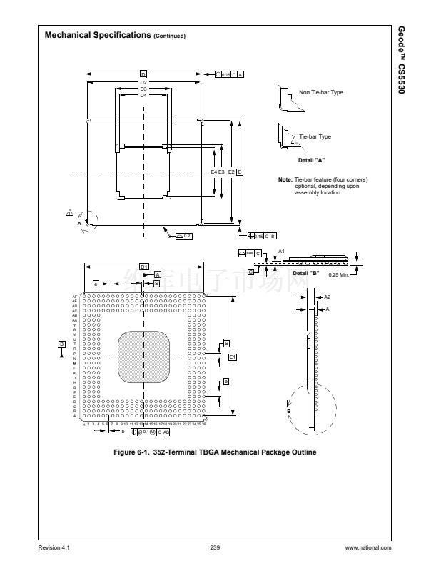 239
239
 240
240
 241
241
