Geode鈩?CS5530
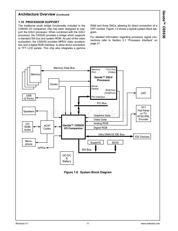
Functional Description
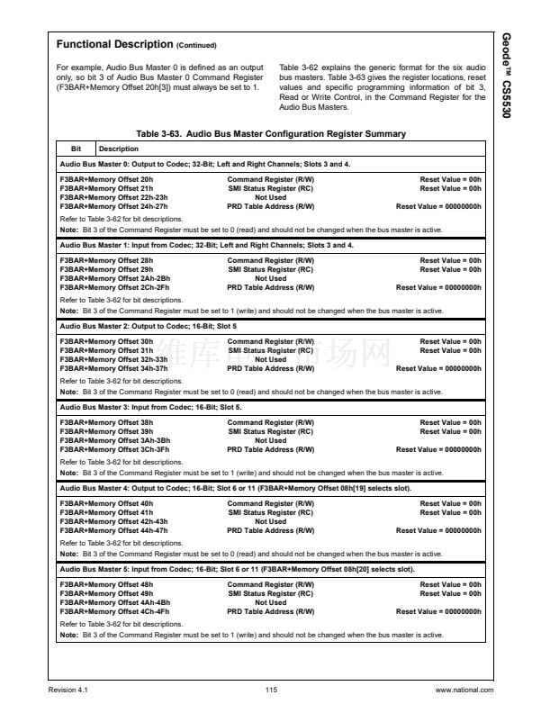
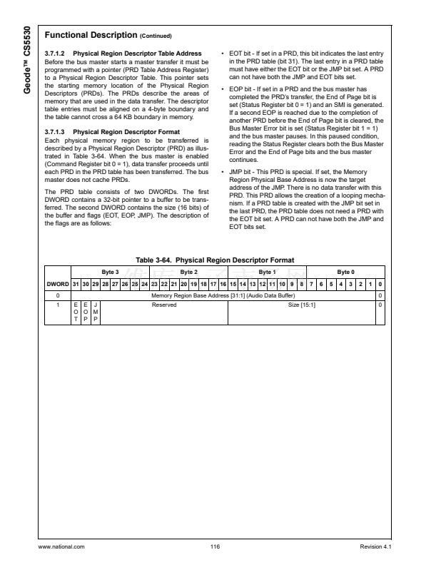
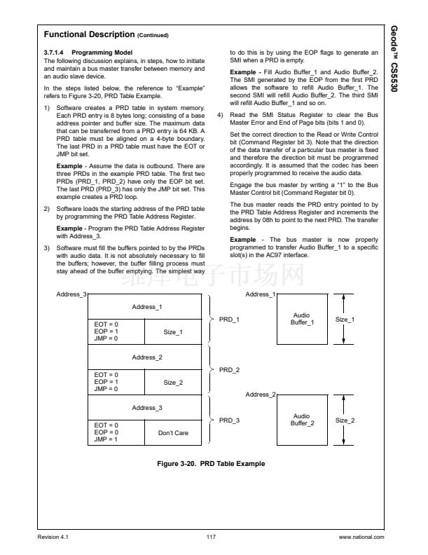
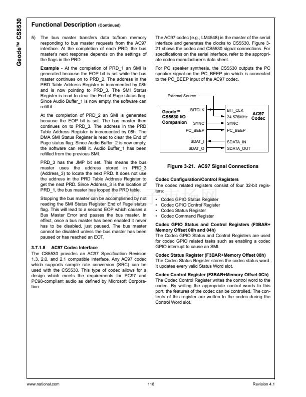
(Continued)
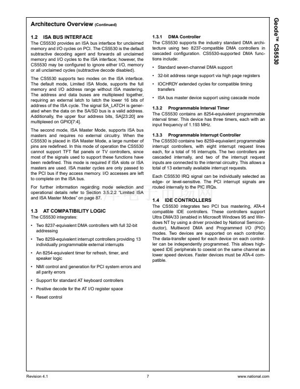
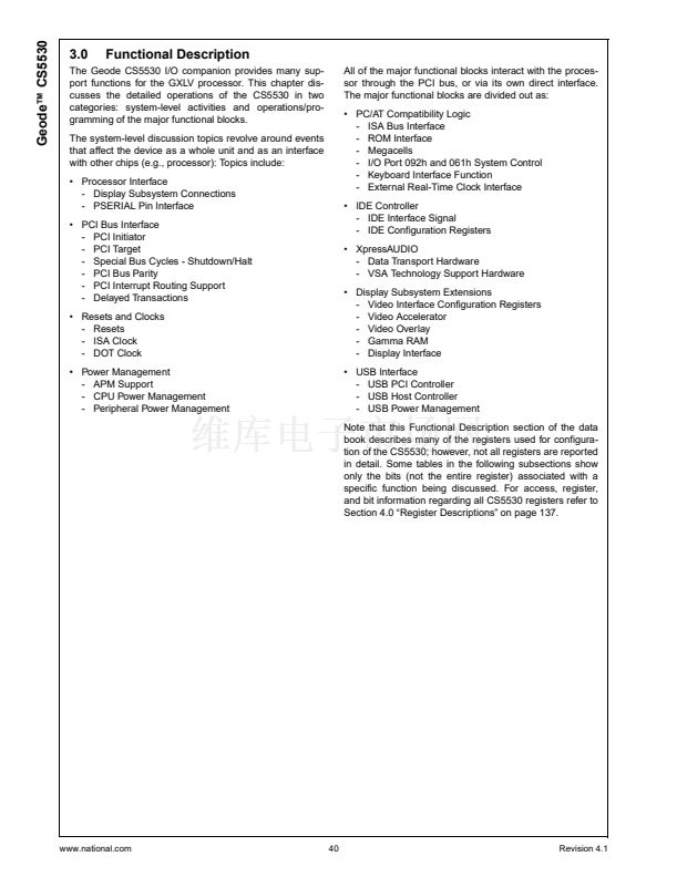
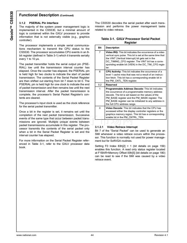
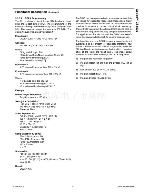
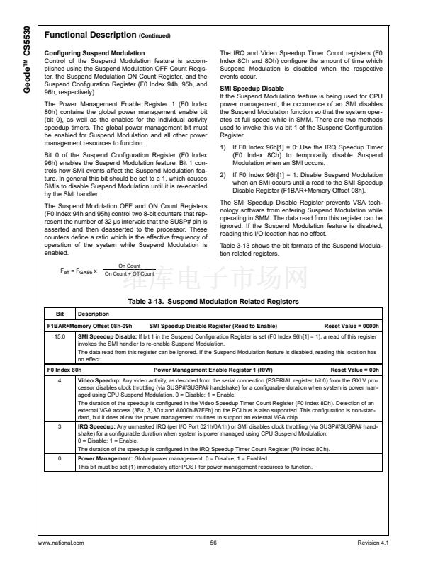
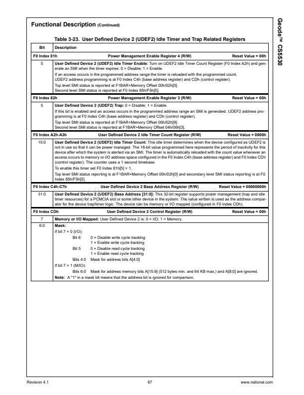
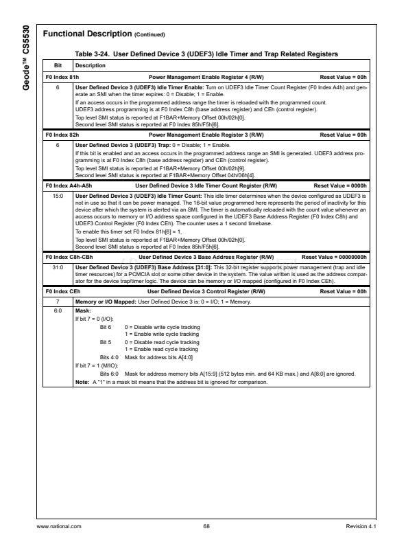
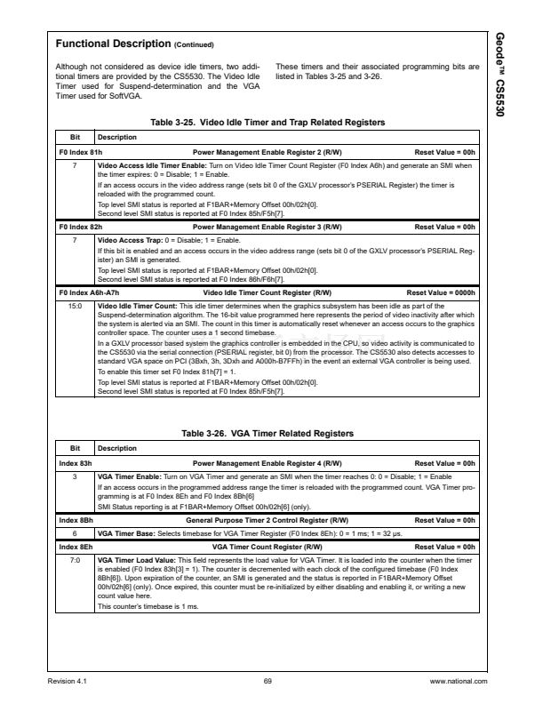
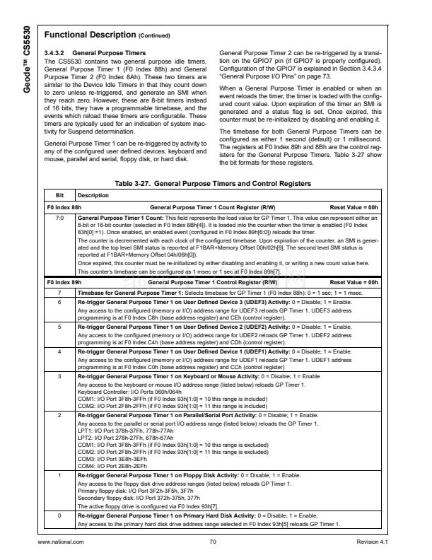
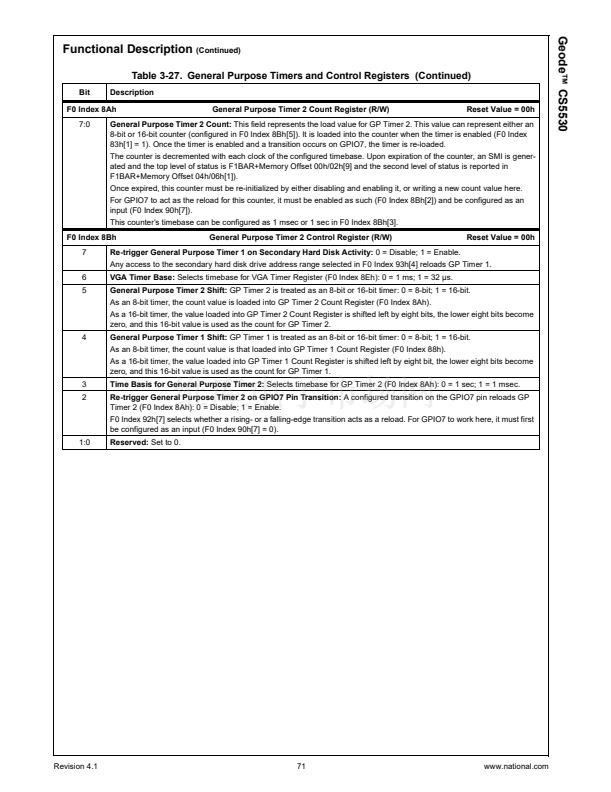
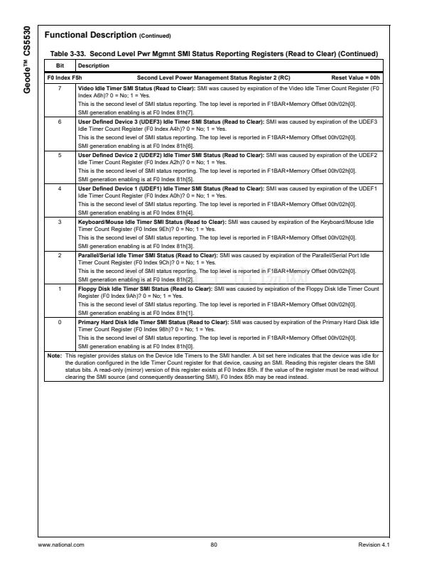
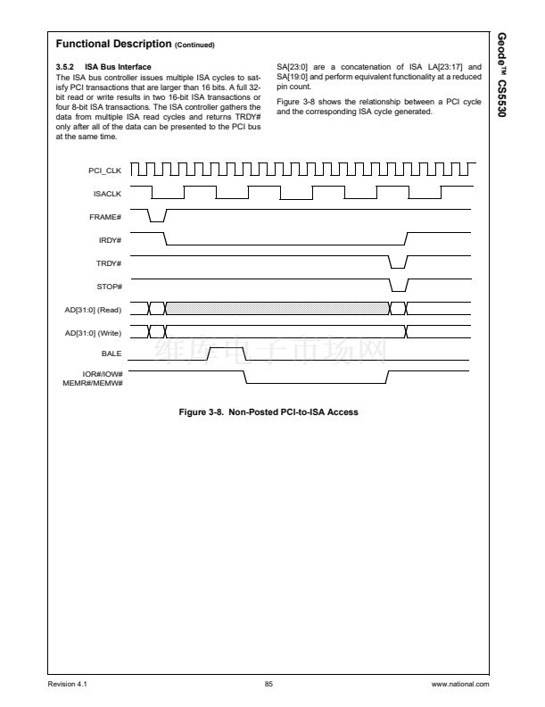
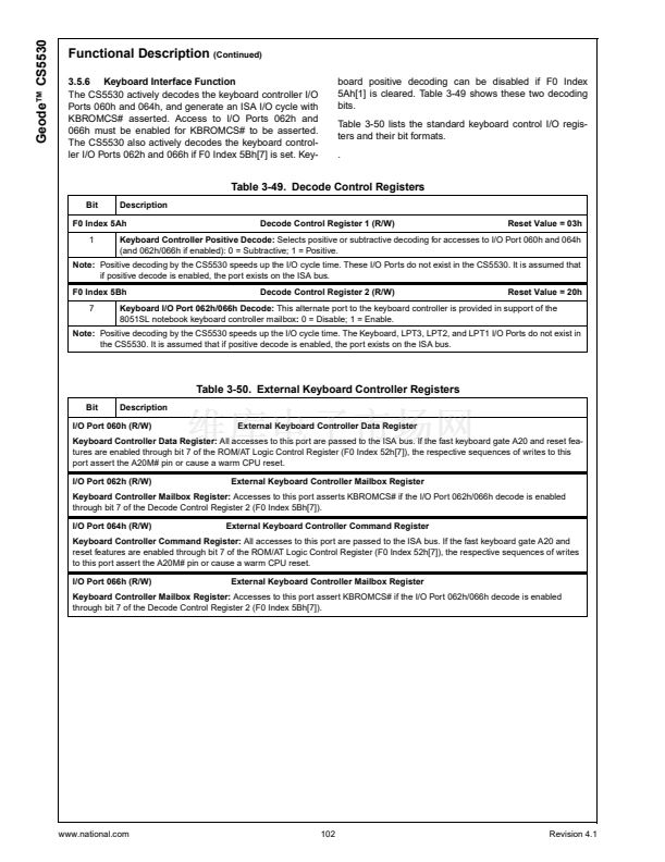
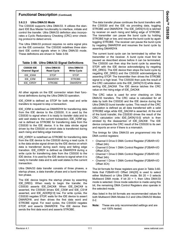
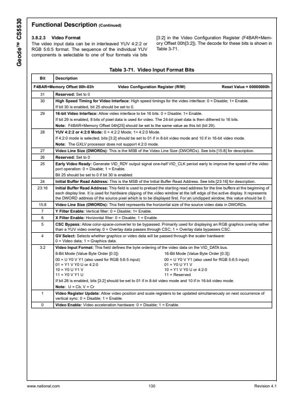
3.4.3.2 General Purpose Timers
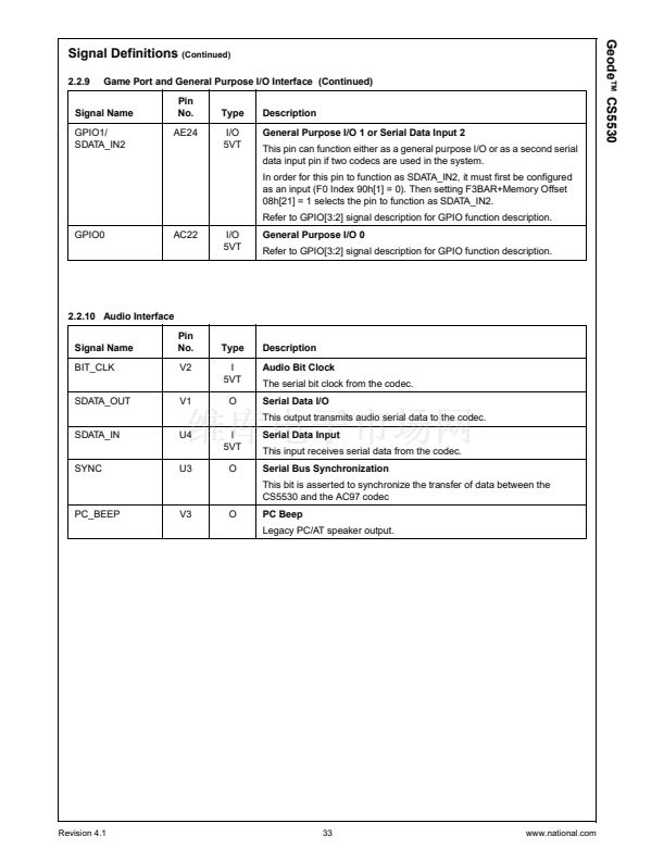
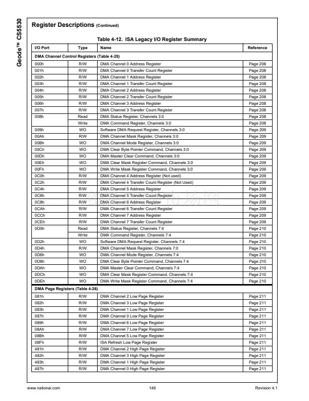
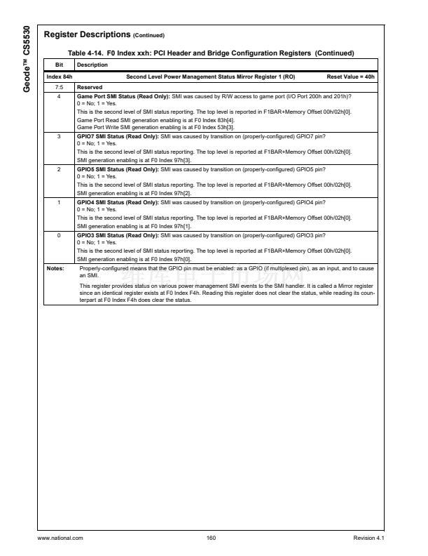
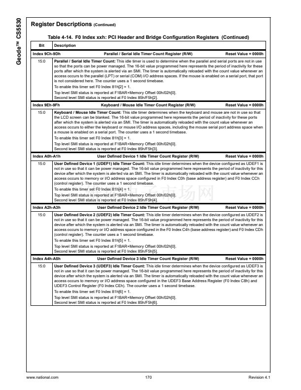
The CS5530 contains two general purpose idle timers,
General Purpose Timer 1 (F0 Index 88h) and General
Purpose Timer 2 (F0 Index 8Ah). These two timers are
similar to the Device Idle Timers in that they count down
to zero unless re-triggered, and generate an SMI when
they reach zero. However, these are 8-bit timers instead
of 16 bits, they have a programmable timebase, and the
events which reload these timers are configurable. These
timers are typically used for an indication of system inac-
tivity for Suspend determination.
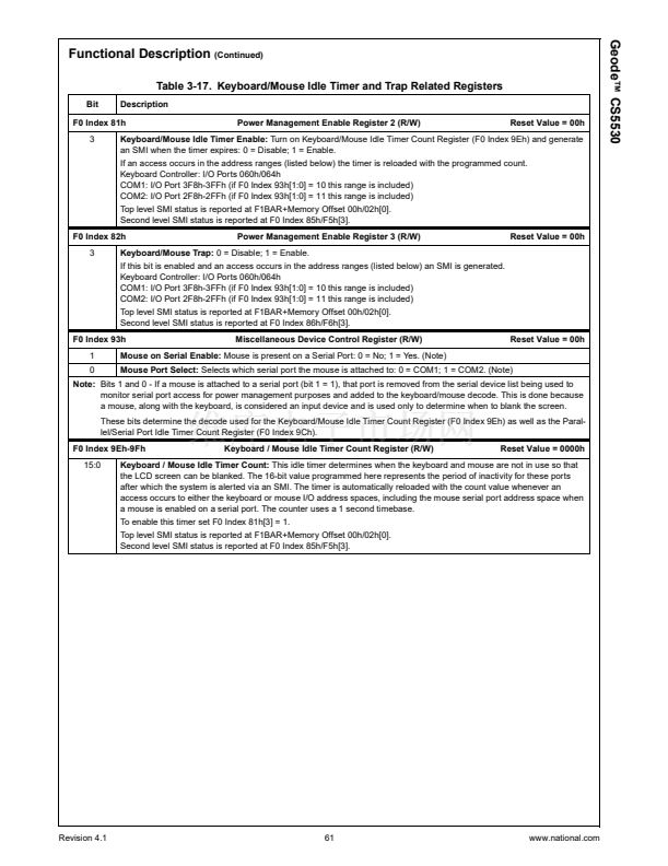
General Purpose Timer 1 can be re-triggered by activity to
any of the configured user defined devices, keyboard and
mouse, parallel and serial, floppy disk, or hard disk.
General Purpose Timer 2 can be re-triggered by a transi-
tion on the GPIO7 pin (if GPIO7 is properly configured).
Configuration of the GPIO7 is explained in Section 3.4.3.4
鈥淕eneral Purpose I/O Pins鈥?on page 73.
When a General Purpose Timer is enabled or when an
event reloads the timer, the timer is loaded with the config-
ured count value. Upon expiration of the timer an SMI is
generated and a status flag is set. Once expired, this
counter must be re-initialized by disabling and enabling it.
The timebase for both General Purpose Timers can be
configured as either 1 second (default) or 1 millisecond.
The registers at F0 Index 89h and 8Bh are the control reg-
isters for the General Purpose Timers. Table 3-27 show
the bit formats for these registers.
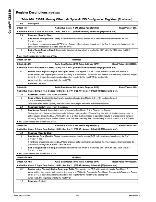
Table 3-27. General Purpose Timers and Control Registers
Bit
Description
General Purpose Timer 1 Count Register (R/W)
Reset Value = 00h
F0 Index 88h
7:0
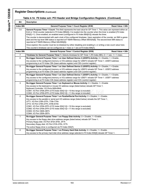
General Purpose Timer 1 Count:
This field represents the load value for GP Timer 1. This value can represent either an
8-bit or 16-bit counter (selected in F0 Index 8Bh[4]). It is loaded into the counter when the timer is enabled (F0 Index
83h[0] =1). Once enabled, an enabled event (configured in F0 Index 89h[6:0]) reloads the timer.
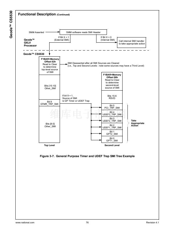
The counter is decremented with each clock of the configured timebase. Upon expiration of the counter, an SMI is gener-
ated and the top level SMI status is reported at F1BAR+Memory Offset 00h/02h[9]. The second level SMI status is
reported at F1BAR+Memory Offset 04h/06h[0]).
Once expired, this counter must be re-initialized by either disabling and enabling it, or writing a new count value here.
This counter鈥檚 timebase can be configured as 1 msec or 1 sec at F0 Index 89h[7].
F0 Index 89h
7
6
General Purpose Timer 1 Control Register (R/W)
Reset Value = 00h
Timebase for General Purpose Timer 1:
Selects timebase for GP Timer 1 (F0 Index 88h): 0 = 1 sec; 1 = 1 msec.
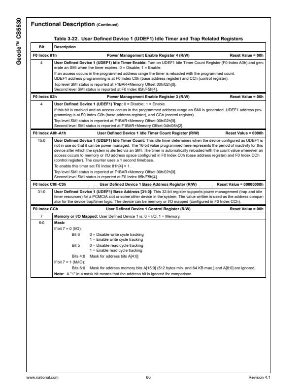
Re-trigger General Purpose Timer 1 on User Defined Device 3 (UDEF3) Activity:
0 = Disable; 1 = Enable.
Any access to the configured (memory or I/O) address range for UDEF3 reloads GP Timer 1. UDEF3 address
programming is at F0 Index C8h (base address register) and CEh (control register).
5
Re-trigger General Purpose Timer 1 on User Defined Device 2 (UDEF2) Activity:
0 = Disable; 1 = Enable.
Any access to the configured (memory or I/O) address range for UDEF2 reloads GP Timer 1. UDEF2 address
programming is at F0 Index C4h (base address register) and CDh (control register).
4
Re-trigger General Purpose Timer 1 on User Defined Device 1 (UDEF1) Activity:
0 = Disable; 1 = Enable.
Any access to the configured (memory or I/O) address range for UDEF1 reloads GP Timer 1. UDEF1 address
programming is at F0 Index C0h (base address register) and CCh (control register)
3
Re-trigger General Purpose Timer 1 on Keyboard or Mouse Activity:
0 = Disable; 1 = Enable
Any access to the keyboard or mouse I/O address range (listed below) reloads GP Timer 1.
Keyboard Controller: I/O Ports 060h/064h
COM1: I/O Port 3F8h-3FFh (if F0 Index 93h[1:0] = 10 this range is included)
COM2: I/O Port 2F8h-2FFh (if F0 Index 93h[1:0] = 11 this range is included)
2
Re-trigger General Purpose Timer 1 on Parallel/Serial Port Activity:
0 = Disable; 1 = Enable.
Any access to the parallel or serial port I/O address range (listed below) reloads the GP Timer 1.
LPT1: I/O Port 378h-37Fh, 778h-77Ah
LPT2: I/O Port 278h-27Fh, 678h-67Ah
COM1: I/O Port 3F8h-3FFh (if F0 Index 93h[1:0] = 10 this range is excluded)
COM2: I/O Port 2F8h-2FFh (if F0 Index 93h[1:0] = 11 this range is excluded)
COM3: I/O Port 3E8h-3EFh
COM4: I/O Port 2E8h-2EFh
1
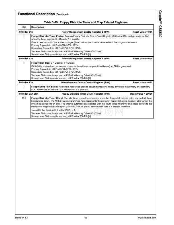
Re-trigger General Purpose Timer 1 on Floppy Disk Activity:
0 = Disable; 1 = Enable.
Any access to the floppy disk drive address ranges (listed below) reloads GP Timer 1.
Primary floppy disk: I/O Port 3F2h-3F5h, 3F7h
Secondary floppy disk: I/O Port 372h-375h, 377h
The active floppy drive is configured via F0 Index 93h[7].
0
Re-trigger General Purpose Timer 1 on Primary Hard Disk Activity:
0 = Disable; 1 = Enable.
Any access to the primary hard disk drive address range selected in F0 Index 93h[5] reloads GP Timer 1.
www.national.com
70
Revision 4.1


 1
1
 2
2
 3
3
 4
4
 5
5
 6
6
 7
7
 8
8
 9
9
 10
10
 11
11
 12
12
 13
13
 14
14
 15
15
 16
16
 17
17
 18
18
 19
19
 20
20
 21
21
 22
22
 23
23
 24
24
 25
25
 26
26
 27
27
 28
28
 29
29
 30
30
 31
31
 32
32
 33
33
 34
34
 35
35
 36
36
 37
37
 38
38
 39
39
 40
40
 41
41
 42
42
 43
43
 44
44
 45
45
 46
46
 47
47
 48
48
 49
49
 50
50
 51
51
 52
52
 53
53
 54
54
 55
55
 56
56
 57
57
 58
58
 59
59
 60
60
 61
61
 62
62
 63
63
 64
64
 65
65
 66
66
 67
67
 68
68
 69
69
 70
70
 71
71
 72
72
 73
73
 74
74
 75
75
 76
76
 77
77
 78
78
 79
79
 80
80
 81
81
 82
82
 83
83
 84
84
 85
85
 86
86
 87
87
 88
88
 89
89
 90
90
 91
91
 92
92
 93
93
 94
94
 95
95
 96
96
 97
97
 98
98
 99
99
 100
100
 101
101
 102
102
 103
103
 104
104
 105
105
 106
106
 107
107
 108
108
 109
109
 110
110
 111
111
 112
112
 113
113
 114
114
 115
115
 116
116
 117
117
 118
118
 119
119
 120
120
 121
121
 122
122
 123
123
 124
124
 125
125
 126
126
 127
127
 128
128
 129
129
 130
130
 131
131
 132
132
 133
133
 134
134
 135
135
 136
136
 137
137
 138
138
 139
139
 140
140
 141
141
 142
142
 143
143
 144
144
 145
145
 146
146
 147
147
 148
148
 149
149
 150
150
 151
151
 152
152
 153
153
 154
154
 155
155
 156
156
 157
157
 158
158
 159
159
 160
160
 161
161
 162
162
 163
163
 164
164
 165
165
 166
166
 167
167
 168
168
 169
169
 170
170
 171
171
 172
172
 173
173
 174
174
 175
175
 176
176
 177
177
 178
178
 179
179
 180
180
 181
181
 182
182
 183
183
 184
184
 185
185
 186
186
 187
187
 188
188
 189
189
 190
190
 191
191
 192
192
 193
193
 194
194
 195
195
 196
196
 197
197
 198
198
 199
199
 200
200
 201
201
 202
202
 203
203
 204
204
 205
205
 206
206
 207
207
 208
208
 209
209
 210
210
 211
211
 212
212
 213
213
 214
214
 215
215
 216
216
 217
217
 218
218
 219
219
 220
220
 221
221
 222
222
 223
223
 224
224
 225
225
 226
226
 227
227
 228
228
 229
229
 230
230
 231
231
 232
232
 233
233
 234
234
 235
235
 236
236
 237
237
 238
238
 239
239
 240
240
 241
241
