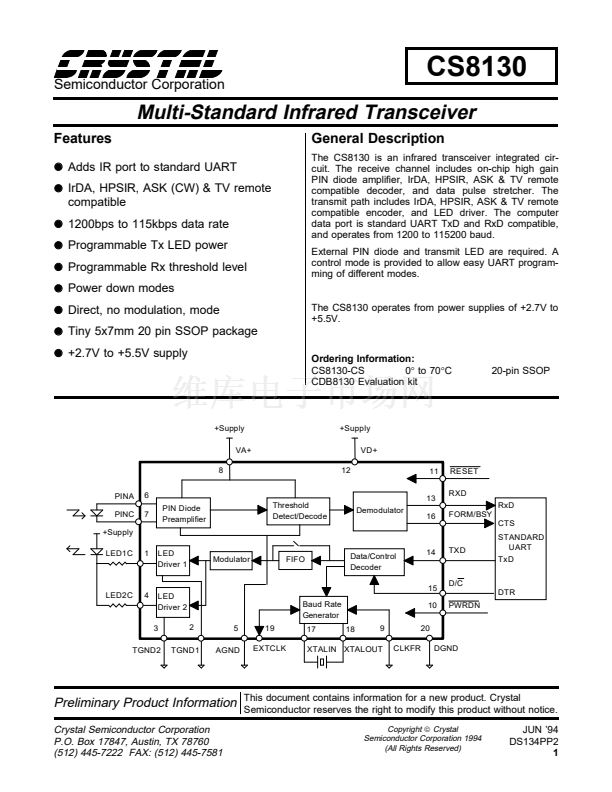
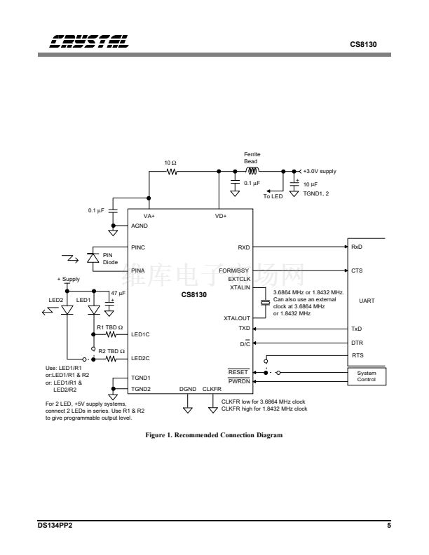
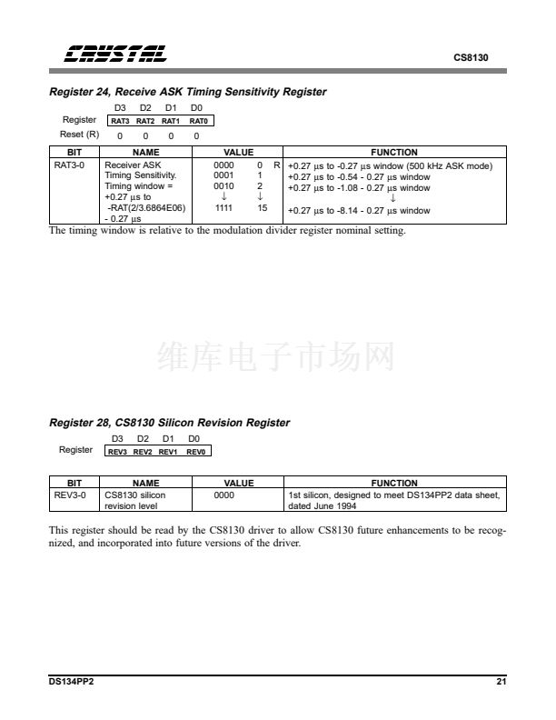
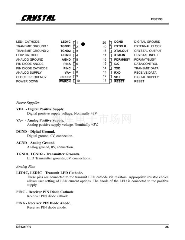
CS8130
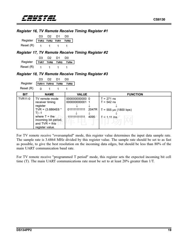
then switch to "programmed T period" mode to
reduce processing overhead in the host CPU.
Clock Generation
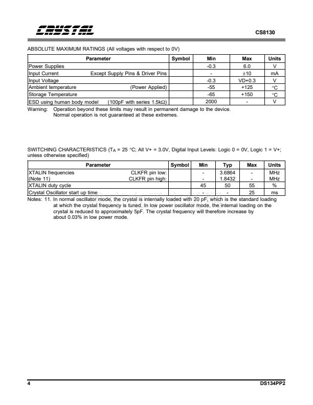
The primary clock required is 3.6864 MHz. This
may be generated by attaching a 3.6864 MHz
crystal to the XTALIN and XTALOUT pins. In
this case, the EXTCLK pin becomes an output,
and may be used to drive external devices. If this
is not required, power may be saved by disabling
the EXTCLK output. The CLKFR pin should be
connected to DGND, which causes the clock cir-
cuits to be configured for 3.6864 MHz operation.
The oscillator has a low power mode. This re-
duces the internal crystal loading capacitance on
XTALOUT and XTALIN. The selection of this
mode is via a bit in Control Register #4. Since
the loading capacitance is reduced, then the crys-
tal frequency will increase by approximately
0.03%.
Alternatively, a 3.6864 MHz clock may be input
into the EXTCLK pin, in which case XTALIN
must be grounded, and XTALOUT is left float-
ing. The CLKFR pin must be connected to
DGND.
If only a 1.8432 MHz clock is available, then it
may be input into the EXTCLK pin and the
CLKFR pin connected to VD+. This causes the
CS8130 to double the incoming 1.8432 MHz
clock to 3.6864 MHz for internal use. XTALIN
must be grounded, and the XTALOUT pin is left
floating.
The CS8130 automatically sets the direction of
the EXTCLK pin. If the crystal oscillator is run-
ning when RESET goes high, then EXTCLK
becomes an output. Since the crystal oscillator
can take up to 25 ms to start, then it follows that
RESET must be held low, with PWRDN high
and power applied, for at least 25 ms. If using an
external clock, then RESET low can be short
(>1
碌s).
Power Down
When the PWRDN pin is brought low, all inter-
nal logic is stopped, including the crystal
oscillator. The power consumption in power
down mode is very low (<1
碌A).
When the
PWRDN pin is brought high, the crystal oscilla-
tor will start. If using the crystal oscillator, allow
25 ms for oscillator start up after bringing
PWRDN high, before trying to use the CS8130.
The control register status will not be changed
by toggling PWRDN.
Control Register #1 allows for individual dis-
abling and enabling of the transmit and receive
sections of the CS8130.
The CS8130 also goes into power down if both
transmit enable and receive enable bits are false,
and the D/C pin is brought high. This allows
control of power down in a pod environment,
where access to the PWRDN pin is difficult. In
this mode, it is possible to select, via a control
register bit, whether the crystal oscillator remains
running, or is powered off. If the oscillator re-
mains running, then it consumes power, but
offers instant wake up. If the oscillator is pow-
ered off, then it consumes no power, but will
take 25 ms to start up.
The PWRDN pin must always be 鈥檋igh鈥?or
鈥檒ow鈥? If this pin is allowed to float, excessive
power consumption may occur. All other digital
inputs may be allowed to float without causing
excessive power consumption in the CS8130 in
power down mode.
The RXD and FORM/BSY output pins may be
programmed to be high, low or float in power
down. This allows maximum flexibility in differ-
ent applications.
DS134PP2
11


 1
1
 2
2
 3
3
 4
4
 5
5
 6
6
 7
7
 8
8
 9
9
 10
10
 11
11
 12
12
 13
13
 14
14
 15
15
 16
16
 17
17
 18
18
 19
19
 20
20
 21
21
 22
22
 23
23
 24
24
 25
25
 26
26
 27
27
 28
28
