Left C. S.
C.S. Data C.S. Data
C. S.
Left C. S.
C. S.
C. S.
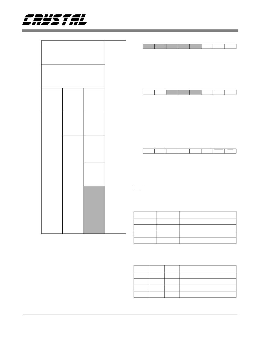
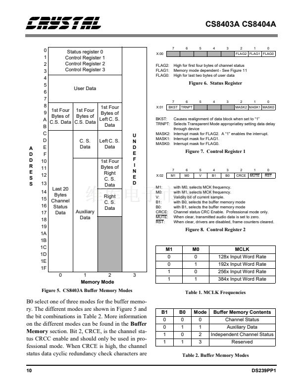
Figure 5. CS8403A Buffer Memory Modes
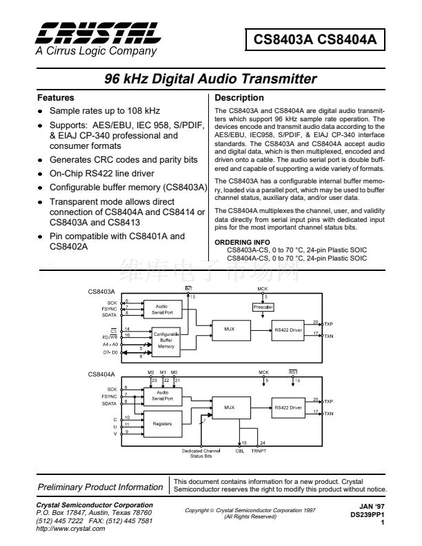
Figure 6. Status Register
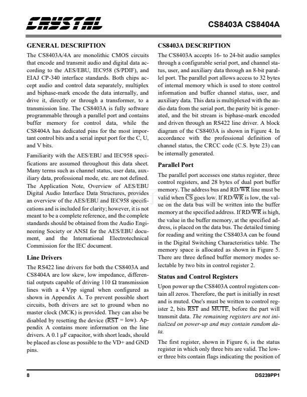
Causes realignment of data block when set to 鈥?鈥?/div>
TRNPT: Selects Transparent Mode appropriatley setting data delay
through device
MASK2: Interrupt mask for FLAG2. A 鈥?鈥?enables the interrupt.
MASK1: Interrupt mask for FLAG1.
MASK0: Interrupt mask for FLAG0.
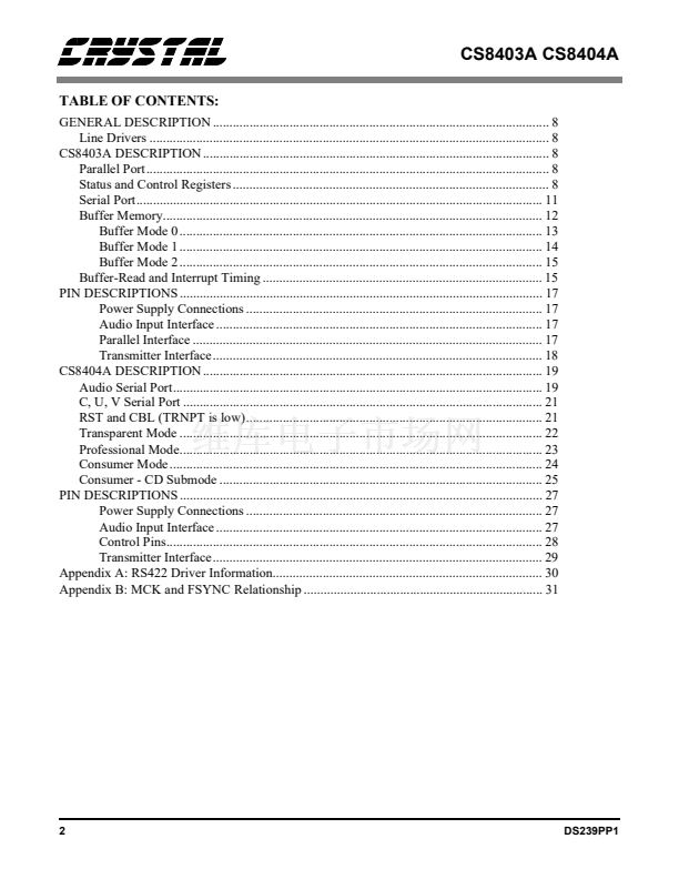
Figure 7. Control Register 1
7
X:02
M1
6
M0
5
V
4
B1
3
B0
2
CRCE
1
MUTE
0
RST
M1:
M0:
V:
B1:
B0:
CRCE:
MUTE:
RST:
with M0, selects MCK frequency.
with M1, selects MCK frequency.
Validity bit of current sample.
with B0, selects the buffer memory mode
with B1, selects the buffer memory mode
Channel status CRC Enable. Professional mode only.
When clear, transmitted audio data is set to zero.
When clear, drivers are disabled, frame counters cleared.
Figure 8. Control Register 2
M1
0
0
3
1
1
M0
0
1
0
1
MCLK
128x Input Word Rate
192x Input Word Rate
256x Input Word Rate
384x Input Word Rate
Table 1. MCLK Frequencies
B0 select one of three modes for the buffer memo-
ry. The different modes are shown in Figure 5 and
the bit combinations in Table 2. More information
on the different modes can be found in the
Buffer
Memory
section. Bit 2, CRCE, is the channel sta-
tus CRCC enable and should only be used in pro-
fessional mode. When CRCE is high, the channel
status data cyclic redundancy check characters are
10
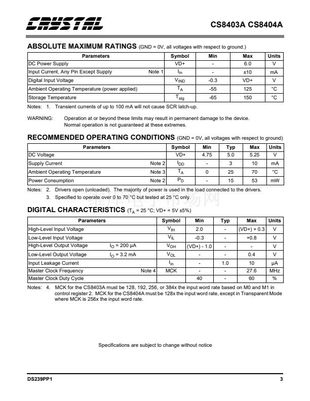
B1
0
0
1
1
B0
0
1
0
1
Mode
0
1
2
3
Buffer Memory Contents
Channel Status
Auxiliary Data
Independent Channel Status
Reserved
Table 2. Buffer Memory Modes
DS239PP1


 1
1
 2
2
 3
3
 4
4
 5
5
 6
6
 7
7
 8
8
 9
9
 10
10
 11
11
 12
12
 13
13
 14
14
 15
15
 16
16
 17
17
 18
18
 19
19
 20
20
 21
21
 22
22
 23
23
 24
24
 25
25
 26
26
 27
27
 28
28
 29
29
 30
30
 31
31
 32
32
 33
33
