CS8403A CS8404A
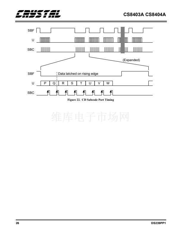
When FSYNC is a word clock (Format 2), CBL is
sampled when left C, U, V are sampled. When
FSYNC is Left/Right, CBL is sampled when left C,
U, V are sampled. The channel status block bound-
ary is reset when CBL transitions from low to high
(based on two successive samples of CBL). MCK
for the CS8404A is normally expected to be 128
times the sample frequency, in the transparent
mode MCK must be 256 Fs.
indicates audio/non-audio; C6 and C7 determine
the sample frequency; and C9 allows the encoded
channel mode to be stereophonic. EM1 and EM0
determine emphasis and encode C2, C3, C4 as
shown in Table 4. The dedicated channel status
pins are read at the appropriate time and are logi-
cally OR鈥檈d with data input on the channel status
port, C. In Transparent Mode, these dedicated
channel status pins are ignored and channel status
bits are input at the C pin.
EM1
0
0
1
1
EM0
0
1
0
1
C2
1
1
1
0
C3
1
1
0
0
C4
1
0
0
0
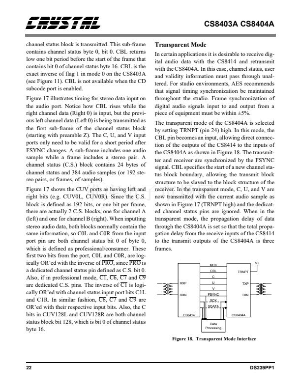
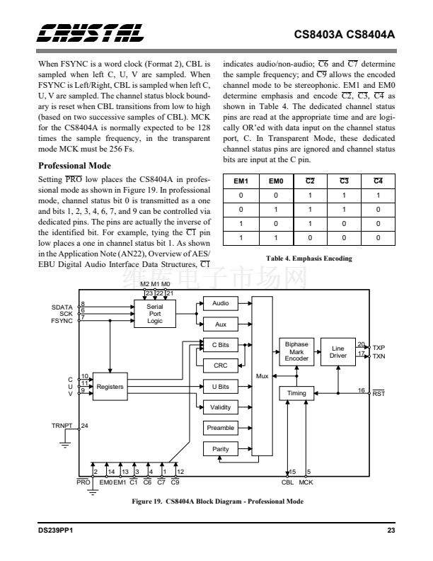
Professional Mode
Setting PRO low places the CS8404A in profes-
sional mode as shown in Figure 19. In professional
mode, channel status bit 0 is transmitted as a one
and bits 1, 2, 3, 4, 6, 7, and 9 can be controlled via
dedicated pins. The pins are actually the inverse of
the identified bit. For example, tying the C1 pin
low places a one in channel status bit 1. As shown
in the Application Note (AN22), Overview of AES/
EBU Digital Audio Interface Data Structures, C1
M2 M1 M0
23 22 21
SDATA
SCK
FSYNC
8
6
7
Serial
Port
Logic
Table 4. Emphasis Encoding
Audio
Aux
C Bits
CRC
Biphase
Mark
Encoder
Mux
20
17
Line
Driver
TXP
TXN
C
U
V
10
11
9
Registers
U Bits
Timing
Validity
16
RST
TRNPT
24
Preamble
Parity
2
PRO
14
13
3
4
1
12
15
5
EM0 EM1 C1 C6 C7 C9
CBL MCK
Figure 19. CS8404A Block Diagram - Professional Mode
DS239PP1
23


 1
1
 2
2
 3
3
 4
4
 5
5
 6
6
 7
7
 8
8
 9
9
 10
10
 11
11
 12
12
 13
13
 14
14
 15
15
 16
16
 17
17
 18
18
 19
19
 20
20
 21
21
 22
22
 23
23
 24
24
 25
25
 26
26
 27
27
 28
28
 29
29
 30
30
 31
31
 32
32
 33
33
