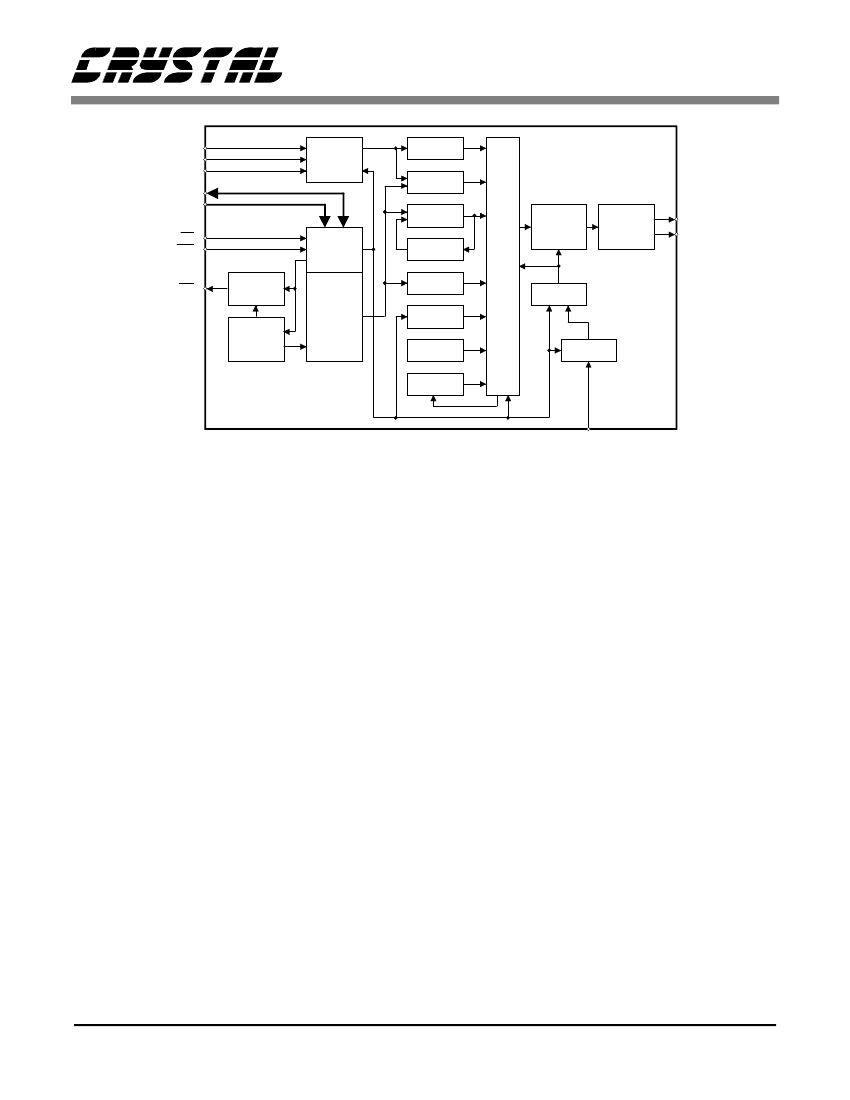
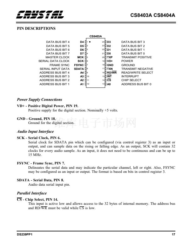
CS8403A CS8404A
SDATA
SCK
FSYNC
D[0:7]
A[0:3]
CS
RD/WR
8
6
7
Serial
Port
Logic
1-4,21-24
9-13
Audio
Aux
C Bits
Biphase
Mark
Encoder
Mux
U Bits
Timing
20
17
14
16
Control
and Flags
4X8
Interrupt
Control
Read
Address
Generator
Buffer
Memory
28 X 8
Line
Driver
TXP
TXN
CRC
INT
15
Validity
IMCK
Preamble
Parity
Prescaler
5
MCK
Figure 4. CS8403A Block Diagram
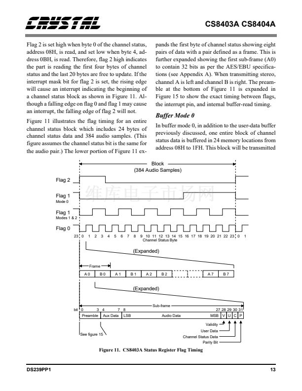
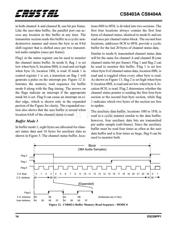
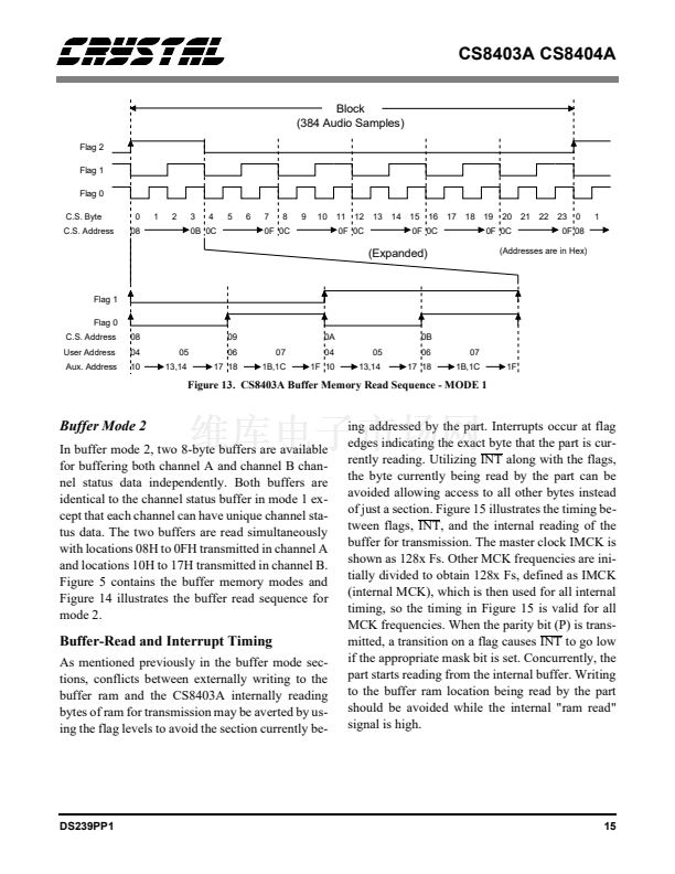
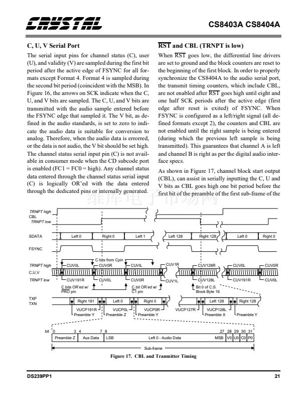
the transmit pointer in the buffer memory. These
flags may be used to avoid contention between the
transmit pointer reading the data and the user up-
dating the buffer memory. Besides indicating the
byte location being transmitted, the flags indicate
the block of memory the part is currently address-
ing, thereby telling the user which block is free to
be written. Each flag has a corresponding mask bit
(control register1) which, when set, allows a transi-
tion on the flag to generate a pulse on the interrupt
pin. Flag 0 and flag 1 cause interrupts on both edges
whereas flag 2 causes an interrupt only on the ris-
ing edge. Timing and further explanation of the
flags can be found in the buffer memory section.
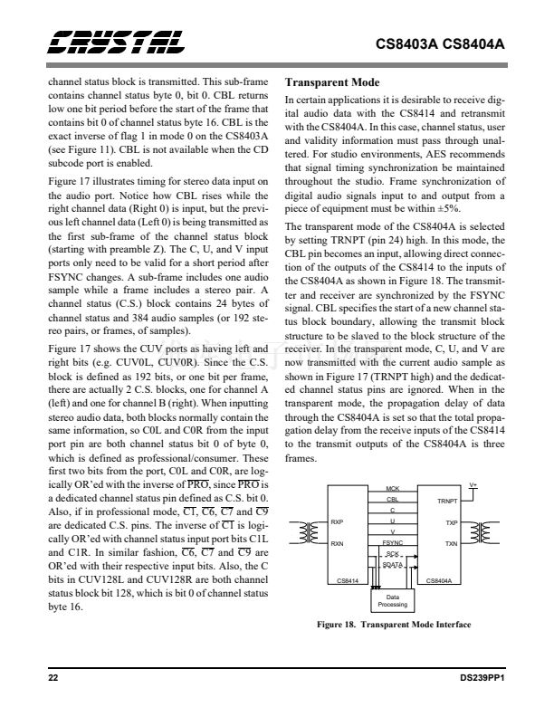
The two most significant bits of control register 1,
BKST and TRNPT, are used for Transparent Mode
operation of the CS8403A. Transparent Mode is
used for those applications where it is useful to
maintain frame alignment between the received
and transmitted audio data signals. In Transparent
Mode (TRNPT="1") the MCK, FSYNC, SCK and
SDATA inputs of the CS8403A can be connected
to their corresponding outputs of the CS8413. In
Transparent Mode, FSYNC synchronizes the trans-
mitter and the receiver. The data delay through the
DS239PP1
CS8403A is set so that three frame delays occur
from the input of the CS8413 to the output of the
CS8403A. In Transparent Mode, 32 SCKs are re-
quired per subframe.
Channel status block alignment between the
CS8413 and the CS8403A is accomplished by set-
ting BKST high at the occurrence of the Flag 2 ris-
ing edge of the CS8413. If FSYNC is a left/right
signal, BKST is sampled once per frame; if
FSYNC is a word clock, BKST is sampled once per
subframe. A low to high transition of BKST (based
on two successive internal samples) resets the
channel status block boundary to the beginning.
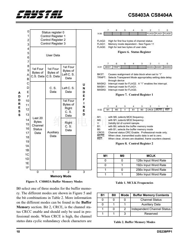
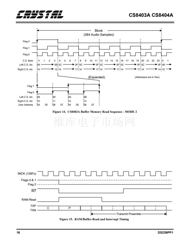
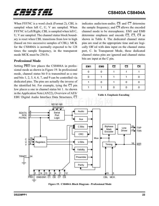
Control register 2, shown in Figure 8, contains var-
ious system level functions. The two most signifi-
cant bits, M1 and M0, select the frequency at the
MCK pin as shown in Table 1. As an example, if
the audio sample frequency is 44.1 kHz and M0
and M1 are both zero, MCK would then be 128x
the audio sample rate or 5.6448 MHz. The next bit
(5) in control register 2, V, indicates the validity of
the current audio sample. According to the digital
audio specifications, V=0 signifies that the audio
signal is suitable for conversion to analog. B1 and
9


 1
1
 2
2
 3
3
 4
4
 5
5
 6
6
 7
7
 8
8
 9
9
 10
10
 11
11
 12
12
 13
13
 14
14
 15
15
 16
16
 17
17
 18
18
 19
19
 20
20
 21
21
 22
22
 23
23
 24
24
 25
25
 26
26
 27
27
 28
28
 29
29
 30
30
 31
31
 32
32
 33
33
