鈥?/div>
)/2.
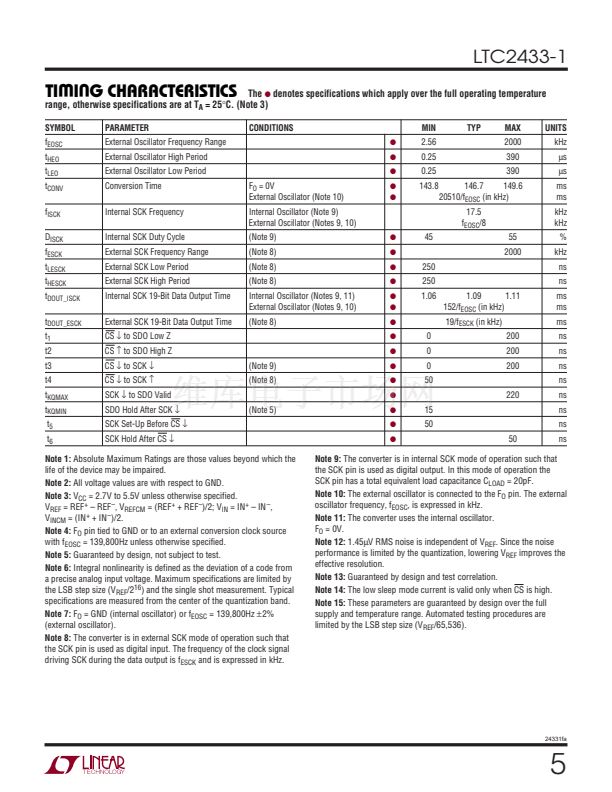
Note 4:
F
O
pin tied to GND or to an external conversion clock source
with f
EOSC
= 139,800Hz unless otherwise specified.
Note 5:
Guaranteed by design, not subject to test.
Note 6:
Integral nonlinearity is defined as the deviation of a code from
a precise analog input voltage. Maximum specifications are limited by
the LSB step size (V
REF
/2
16
) and the single shot measurement. Typical
specifications are measured from the center of the quantization band.
Note 7:
F
O
= GND (internal oscillator) or f
EOSC
= 139,800Hz
卤2%
(external oscillator).
Note 8:
The converter is in external SCK mode of operation such that
the SCK pin is used as digital input. The frequency of the clock signal
driving SCK during the data output is f
ESCK
and is expressed in kHz.
UW
CONDITIONS
q
q
q
q
q
MIN
2.56
0.25
0.25
143.8
TYP
MAX
2000
390
390
UNITS
kHz
碌s
碌s
ms
ms
kHz
kHz
146.7
149.6
20510/f
EOSC
(in kHz)
17.5
f
EOSC
/8
45
250
250
1.06
55
2000
%
kHz
ns
ns
1.09
1.11
152/f
EOSC
(in kHz)
19/f
ESCK
(in kHz)
200
200
200
220
ms
ms
ms
ns
ns
ns
ns
ns
ns
ns
0
0
0
50
15
50
50
ns
Note 9:
The converter is in internal SCK mode of operation such that
the SCK pin is used as digital output. In this mode of operation the
SCK pin has a total equivalent load capacitance C
LOAD
= 20pF.
Note 10:
The external oscillator is connected to the F
O
pin. The external
oscillator frequency, f
EOSC
, is expressed in kHz.
Note 11:
The converter uses the internal oscillator.
F
O
= 0V.
Note 12:
1.45碌V RMS noise is independent of V
REF
. Since the noise
performance is limited by the quantization, lowering V
REF
improves the
effective resolution.
Note 13:
Guaranteed by design and test correlation.
Note 14:
The low sleep mode current is valid only when CS is high.
Note 15:
These parameters are guaranteed by design over the full
supply and temperature range. Automated testing procedures are
limited by the LSB step size (V
REF
/65,536).
24331fa
5


 1
1
 2
2
 3
3
 4
4
 5
5
 6
6
 7
7
 8
8
 9
9
 10
10
 11
11
 12
12
 13
13
 14
14
 15
15
 16
16
 17
17
 18
18
 19
19
 20
20
 21
21
 22
22
 23
23
 24
24
 25
25
 26
26
 27
27
 28
28
