LMH1982
setting EN_TOF_RST = 0 after the output alignment and be-
fore the subsequent output frame.
3.0 MODES OF OPERATION
The mode of operation describes the operation of the VCXO
PLL, which can operate in either Free Run mode or Genlock
mode depending on the GNLK bit setting. If desired, the
GENLOCK input pin can be instead used to control the mode
of operation by initially setting I
2
C_GNLK = 0 (register 00h).
3.1 Free Run Mode
The LMH1982 will enter Free Run mode when GNLK is set to
0. In Free Run mode, the VCXO will be free-running and in-
dependent of the input reference, and the output clocks will
maintain phase lock to the VCXO clock reference. Therefore,
the output clocks will have the same accuracy as the VCXO
clock reference.
The LMH1982 provides the designer with the option to define
the VCXO's free run control voltage by external biasing of the
VC_FREERUN input (pin 1). The analog bias voltage applied
to the VC_FREERUN input will be internally connected to the
LPF output (pin 31) though a low impedance switch, as shown
in section
Functional Block Diagram.
The resultant voltage at
the LPF output will drive the control input of the VCXO to set
its free run output frequency. Thus, the pull range of the VCXO
imparts the same pull range on the free run output clocks.
If VC_FREERUN is left floating, the VCXO control voltage will
be pulled to GND potential as the residual charge stored
across the loop filter will discharge through any existing leak-
age path.
3.2 Genlock Mode
The LMH1982 will enter Genlock mode when GNLK is set to
1. In Genlock mode, the VCXO PLL can be phase locked to
the reference H sync input of the selected port; once the
VCXO PLL clock reference is locked and stable, the output
clocks and TOF pulse can be aligned and phase locked to the
reference. The LMH1982 supports cross-locking, which al-
lows the outputs to be frame-locked to a reference format that
is different from the output format.
To genlock the outputs, the following programming sequence
is suggested:
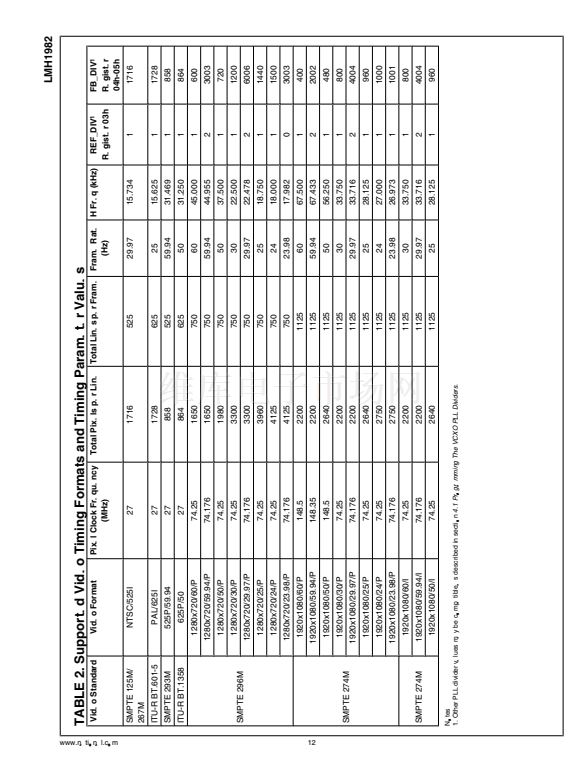
1. Program the output clock frequency for the desired
output format. Refer to section
4.1 Programming The
VCXO PLL Dividers.
2. Program the output TOF timing for the desired output
format. Refer to section
5.2 Programming The Output
Timing Format.
It is necessary to complete this step for
proper output clock alignment even when the TOF pulse
is not required.
3. Program the VCXO PLL divider registers for the input
reference format. Refer to section
4.1 Programming The
VCXO PLL Dividers.
4. Program GNLK = 1 to enable Genlock mode. See the
note below.
5. Program the output alignment to the desired reference
frame. Refer to section
5.3 Programming The Output
Alignment Sequence.
Note:
When Genlock mode is enabled, the LMH1982 will at-
tempt to phase lock the PLLs to the input reference regardless
of input timing stability. Timing errors or instability on the in-
puts will cause the PLLs and outputs to also have instability.
If output stability is a consideration during periods of input
uncertainty, it is suggested to gate off the input signals from
the LMH1982 until they are completely stable. Input signal
gating can be achieved externally using a discrete or FPGA
www.national.com
10
logic buffer with Hi-Z (tri-state) output and a pull-up or pull-
down resistor, depending on the input pulse signal polarity.
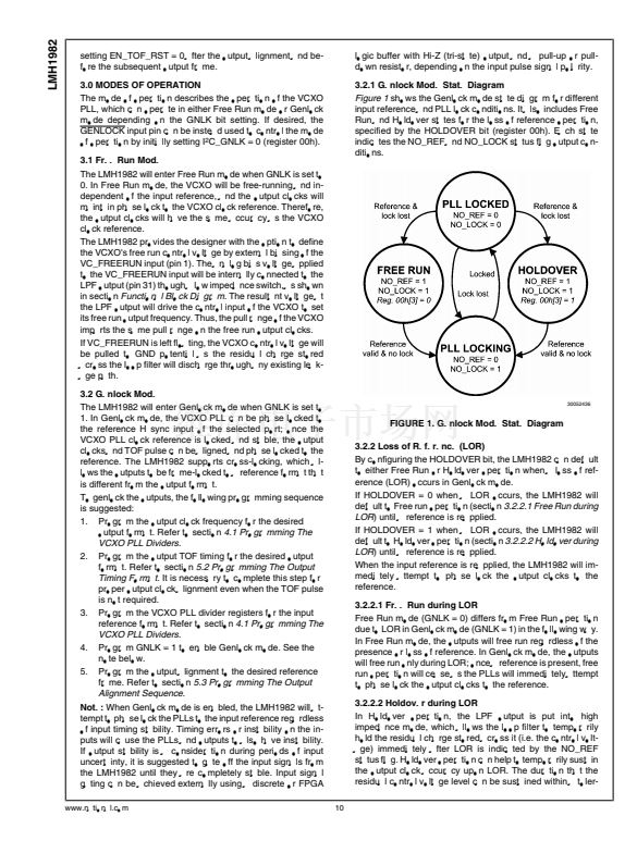
3.2.1 Genlock Mode State Diagram
Figure 1
shows the Genlock mode state diagram for different
input reference and PLL lock conditions. It also includes Free
Run and Holdover states for the loss of reference operation,
specified by the HOLDOVER bit (register 00h). Each state
indicates the NO_REF and NO_LOCK status flag output con-
ditions.
30052436
FIGURE 1. Genlock Mode State Diagram
3.2.2 Loss of Reference (LOR)
By configuring the HOLDOVER bit, the LMH1982 can default
to either Free Run or Holdover operation when a loss of ref-
erence (LOR) occurs in Genlock mode.
If HOLDOVER = 0 when a LOR occurs, the LMH1982 will
default to Free run operation (section
3.2.2.1 Free Run during
LOR)
until a reference is reapplied.
If HOLDOVER = 1 when a LOR occurs, the LMH1982 will
default to Holdover operation (section
3.2.2.2 Holdover during
LOR)
until a reference is reapplied.
When the input reference is reapplied, the LMH1982 will im-
mediately attempt to phase lock the output clocks to the
reference.
3.2.2.1 Free Run during LOR
Free Run mode (GNLK = 0) differs from Free Run operation
due to LOR in Genlock mode (GNLK = 1) in the following way.
In Free Run mode, the outputs will free run regardless of the
presence or loss of reference. In Genlock mode, the outputs
will free run only during LOR; once a reference is present, free
run operation will cease as the PLLs will immediately attempt
to phase lock the output clocks to the reference.
3.2.2.2 Holdover during LOR
In Holdover operation, the LPF output is put into high
impedance mode, which allows the loop filter to temporarily
hold the residual charge stored across it (i.e. the control volt-
age) immediately after LOR is indicated by the NO_REF
status flag. Holdover operation can help to temporarily sustain
the output clock accuracy upon LOR. The duration that the
residual control voltage level can be sustained within a toler-


 1
1
 2
2
 3
3
 4
4
 5
5
 6
6
 7
7
 8
8
 9
9
 10
10
 11
11
 12
12
 13
13
 14
14
 15
15
 16
16
 17
17
 18
18
 19
19
 20
20
 21
21
 22
22
 23
23
 24
24
 25
25
 26
26
 27
27
 28
28
