鈭?/div>
25% PWM.
In addition to the R25 thermistor rating, sometimes a data
sheet will provide the ratio of R25/R50 (resistance at 25掳C
divided by resistance at 50掳C) is given. Sometimes this is
given as an R0/R50 ratio. Other data sheet contents either
specify or help the user determine device resistance at
arbitrary temperatures. The thermistor interface to the MIC502
usually consists of the thermistor and two resistors.
100
80
60
40
20
0
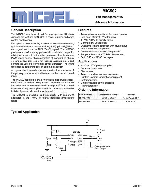
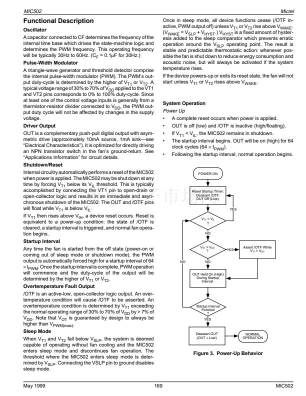
Applications Information
The Typical Application drawing on page 1 illustrates a typical
application circuit for the MIC502. Interfacing the MIC502
with a system consists of the following steps:
1. Selecting a temperature sensor
2. Interfacing the temperature sensor to the VT1 input
3 Selecting a fan-drive transistor, and base-drive current
limit resistor
4. Deciding what to do with the Secondary
Fan-Control Input
5. Making use of the Overtemperature Fault Output.
Temperature Sensor Selection
Temperature sensor T1 is a negative temperature coefficient
(NTC) thermistor. The MIC502 can be interfaced with either
a negative or positive tempco thermistor; however, a nega-
tive temperature coefficient thermistor typically costs less
than its equivalent positive tempco counterpart. While a
variety of thermistors can be used in this application, the
following paragraphs reveal that those with an R25 rating
(resistance at 25掳C) of from about 50k鈩?to 100k鈩?lend
themselves nicely to an interface network that requires only
a modest current drain. Keeping the thermistor bias current
low not only indicates prudent design; it also prevents self-
heating of the sensor from becoming an additional design
consideration. It is assumed that the thermistor will be located
within the system power supply, which most likely also
houses the speed-controlled fan.
Temperature Sensor Interface
As shown by the Electrical Characteristics table, the working
voltage for input VT1 is specified as a percentage of V
DD
. This
conveniently frees the designer from having to be concerned
with interactions resulting from variations in the supply volt-
age. By design, the operating range of VT1 is from about 30%
of V
DD
to about 70% of V
DD
.
V
PWM(min)
= V
PWM(max)
鈥?V
PWM(span)
When V
T1
= V
PWM(max)
鈮?/div>
0.7V
DD
, a 100% duty-cycle motor
drive signal is generated. Conversely, when V
T1
= V
PWM(min)
鈮?/div>
0.3V
DD
, the motor-drive signal has a 0% duty cycle.
Resistor voltage divider R1 || T1, R2 in the Typical Application
diagram is designed to preset V
T1
to a value of V
PWM
that
corresponds to the slowest desired fan speed when the
resistance of thermistor T1 is at its highest (cold) value. As
temperature rises the resistance of T1 decreases and V
T1
increases because of the parallel connection of R1 and T1.
Since V
T1
= V
PWM(min)
represents a stopped fan (0% duty-
cycle drive), and since it is foreseen that at least some cooling
will almost always be required, the lowest voltage applied to
the VT1 input will normally be somewhat higher than 0.3V
DD
(or >V
PWM(min)
). It is assumed that the system will be in sleep
mode rather than operate the fan at a very low duty cycle
(<< 25%). Operation at very low duty cycle results in relatively
little airflow. Sleep mode should be used to reduce acoustic
noise when the system is cool. For a given minimum desired
fan speed, a corresponding V
T1(min)
can be determined via
the following observation:
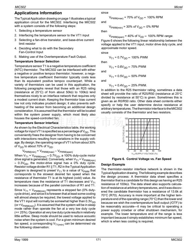
DUTY CYCLE (%)
0
20
40
60
80
100
V
T1
/SUPPLY VOLTAGE (%)
Figure 6. Control Voltage vs. Fan Speed
Design Example
The thermistor-resistor interface network is shown in the
Typical Application drawing. The following example describes
the design process: A thermistor data sheet specifies a
thermistor that is a candidate for this design as having an R25
resistance of 100k鈩? The data sheet also supports calcula-
tion of resistance at arbitrary temperatures, and it was discov-
ered the candidate thermistor has a resistance of 13.6k at
70掳C (R70). Accuracy is more important at the higher tem-
perature end of the operating range (70掳C) than the lower end
because we wish the overtemperature fault output (/OTF) to
be reasonably accurate鈥攊t may be critical to operating a
power supply crowbar or other shutdown mechanism, for
example. The lower temperature end of the range is less
important because it simply establishes minimum fan speed,
which is when less cooling is required.
May 1999
171
MIC502


 1
1
 2
2
 3
3
 4
4
 5
5
 6
6
 7
7
 8
8
 9
9
 10
10
 11
11
