Philips Semiconductors
SC16C654B/654DB
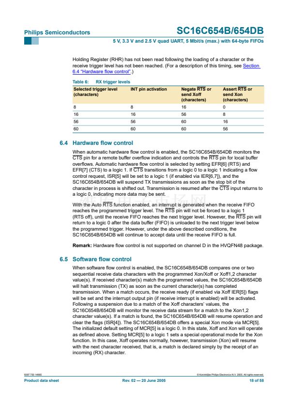
5 V, 3.3 V and 2.5 V quad UART, 5 Mbit/s (max.) with 64-byte FIFOs
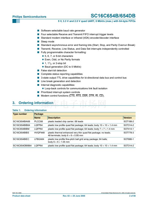
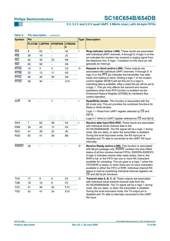
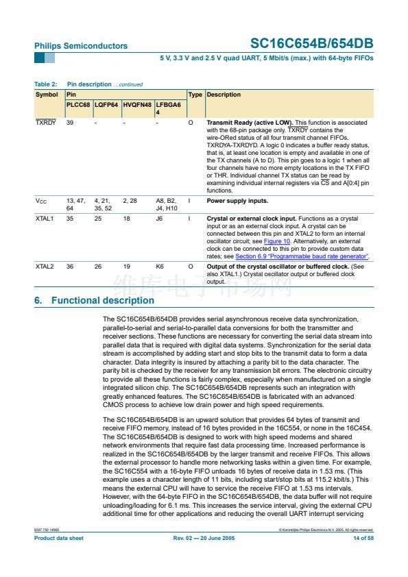
Table 2:
Symbol
Pin description
鈥ontinued
Pin
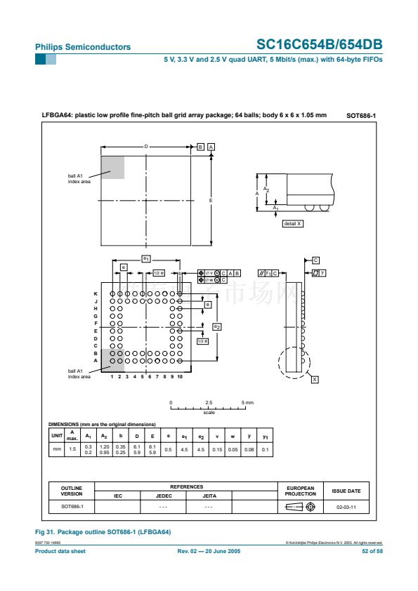
PLCC68 LQFP64 HVQFN48 LFBGA6
4
Type Description
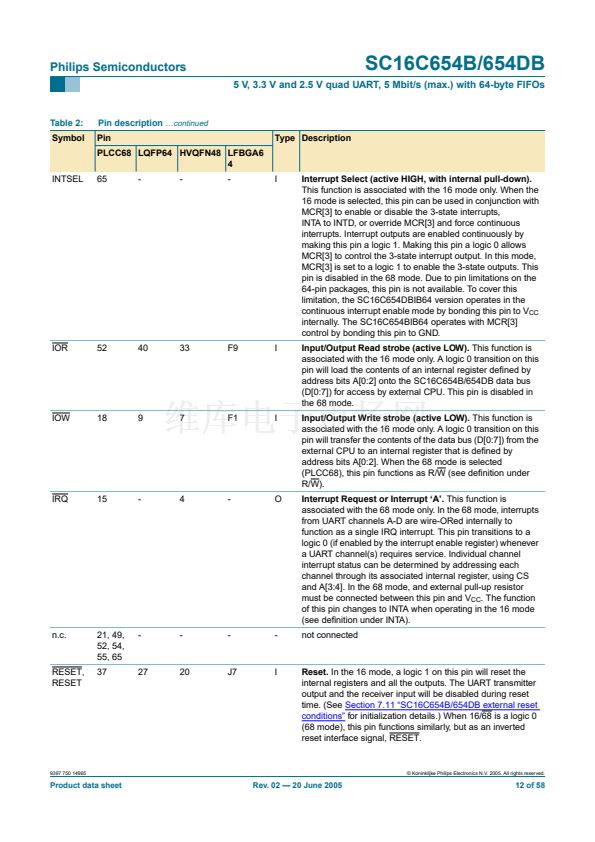
INTSEL
65
-
-
-
I
Interrupt Select (active HIGH, with internal pull-down).
This function is associated with the 16 mode only. When the
16 mode is selected, this pin can be used in conjunction with
MCR[3] to enable or disable the 3-state interrupts,
INTA to INTD, or override MCR[3] and force continuous
interrupts. Interrupt outputs are enabled continuously by
making this pin a logic 1. Making this pin a logic 0 allows
MCR[3] to control the 3-state interrupt output. In this mode,
MCR[3] is set to a logic 1 to enable the 3-state outputs. This
pin is disabled in the 68 mode. Due to pin limitations on the
64-pin packages, this pin is not available. To cover this
limitation, the SC16C654DBIB64 version operates in the
continuous interrupt enable mode by bonding this pin to V
CC
internally. The SC16C654BIB64 operates with MCR[3]
control by bonding this pin to GND.
Input/Output Read strobe (active LOW).
This function is
associated with the 16 mode only. A logic 0 transition on this
pin will load the contents of an internal register de铿乶ed by
address bits A[0:2] onto the SC16C654B/654DB data bus
(D[0:7]) for access by external CPU. This pin is disabled in
the 68 mode.
Input/Output Write strobe (active LOW).
This function is
associated with the 16 mode only. A logic 0 transition on this
pin will transfer the contents of the data bus (D[0:7]) from the
external CPU to an internal register that is de铿乶ed by
address bits A[0:2]. When the 68 mode is selected
(PLCC68), this pin functions as R/W (see de铿乶ition under
R/W).
Interrupt Request or Interrupt 鈥楢鈥?
This function is
associated with the 68 mode only. In the 68 mode, interrupts
from UART channels A-D are wire-ORed internally to
function as a single IRQ interrupt. This pin transitions to a
logic 0 (if enabled by the interrupt enable register) whenever
a UART channel(s) requires service. Individual channel
interrupt status can be determined by addressing each
channel through its associated internal register, using CS
and A[3:4]. In the 68 mode, and external pull-up resistor
must be connected between this pin and V
CC
. The function
of this pin changes to INTA when operating in the 16 mode
(see de铿乶ition under INTA).
not connected
IOR
52
40
33
F9
I
IOW
18
9
7
F1
I
IRQ
15
-
4
-
O
n.c.
21, 49,
52, 54,
55, 65
37
-
-
-
-
RESET,
RESET
27
20
J7
I
Reset.
In the 16 mode, a logic 1 on this pin will reset the
internal registers and all the outputs. The UART transmitter
output and the receiver input will be disabled during reset
time. (See
Section 7.11 鈥淪C16C654B/654DB external reset
conditions鈥?/span>
for initialization details.) When 16/68 is a logic 0
(68 mode), this pin functions similarly, but as an inverted
reset interface signal, RESET.
9397 750 14965
漏 Koninklijke Philips Electronics N.V. 2005. All rights reserved.
Product data sheet
Rev. 02 鈥?20 June 2005
12 of 58


 1
1
 2
2
 3
3
 4
4
 5
5
 6
6
 7
7
 8
8
 9
9
 10
10
 11
11
 12
12
 13
13
 14
14
 15
15
 16
16
 17
17
 18
18
 19
19
 20
20
 21
21
 22
22
 23
23
 24
24
 25
25
 26
26
 27
27
 28
28
 29
29
 30
30
 31
31
 32
32
 33
33
 34
34
 35
35
 36
36
 37
37
 38
38
 39
39
 40
40
 41
41
 42
42
 43
43
 44
44
 45
45
 46
46
 47
47
 48
48
 49
49
 50
50
 51
51
 52
52
 53
53
 54
54
 55
55
 56
56
 57
57
 58
58
