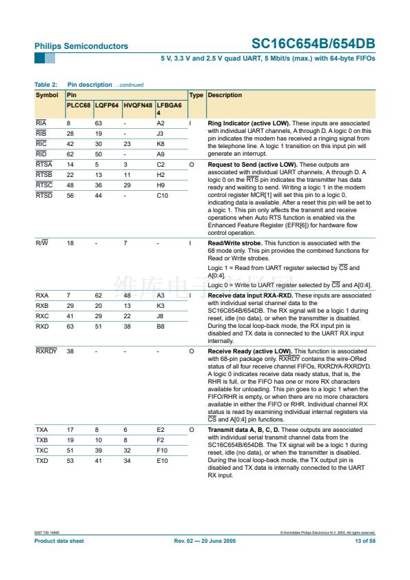
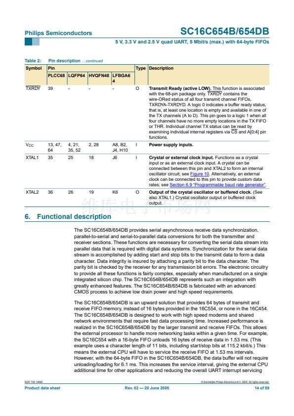
Philips Semiconductors
SC16C654B/654DB
5 V, 3.3 V and 2.5 V quad UART, 5 Mbit/s (max.) with 64-byte FIFOs
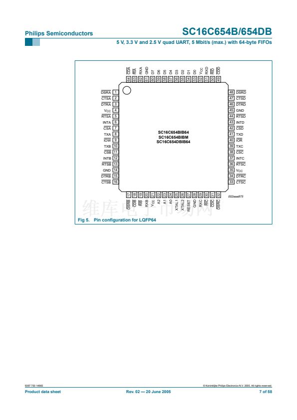
6.1 Interface options
Two user interface modes are selectable for the PLCC68 package. These interface modes
are designated as the 鈥?6 mode鈥?and the 鈥?8 mode鈥? This nomenclature corresponds to the
early 16C454/554 and 68C454/554 package interfaces respectively.
6.1.1 The 16 mode interface
The 16 mode con铿乬ures the package interface pins for connection as a standard
16 series (Intel) device and operates similar to the standard CPU interface available on
the 16C454/554. In the 16 mode (pin 16/68 = logic 1), each UART is selected with
individual chip select (CSx) pins, as shown in
Table 3.
Table 3:
CSA
1
0
1
1
1
Serial port channel selection, 16 mode interface
CSB
1
1
0
1
1
CSC
1
1
1
0
1
CSD
1
1
1
1
0
UART channel
none
A
B
C
D
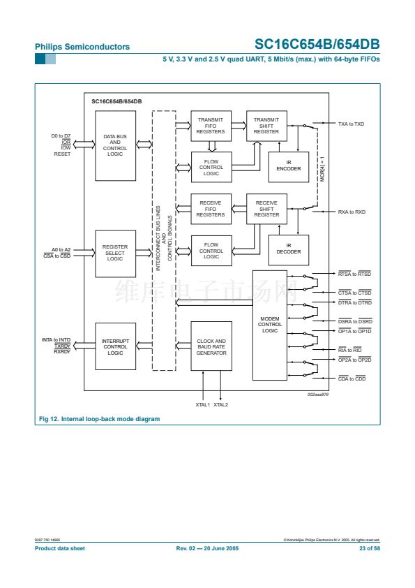
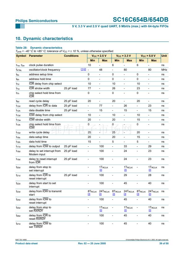
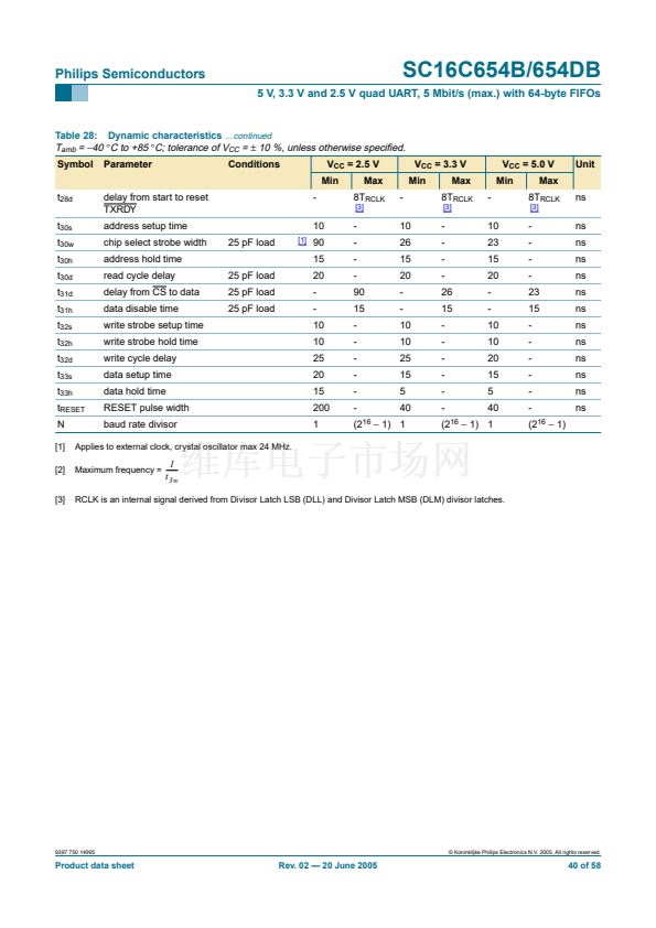
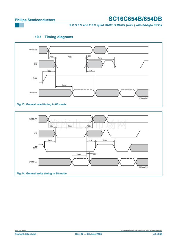
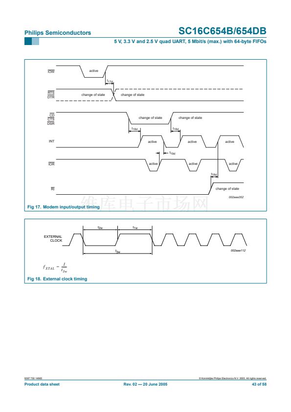
6.1.2 The 68 mode interface
The 68 mode con铿乬ures the package interface pins for connection with Motorola, and
other popular microprocessor bus types. The interface operates similar to the
68C454/554. In this mode, the SC16C654B/654DB decodes two additional addresses,
A3-A4, to select one of the four UART ports. The A[3:4] address decode function is used
only when in the 68 mode (16/68 = logic 0), and is shown in
Table 4.
Table 4:
CS
1
0
0
0
0
Serial port channel selection, 68 mode interface
A4
n/a
0
0
1
1
A3
n/a
0
1
0
1
UART channel
none
A
B
C
D
9397 750 14965
漏 Koninklijke Philips Electronics N.V. 2005. All rights reserved.
Product data sheet
Rev. 02 鈥?20 June 2005
16 of 58


 1
1
 2
2
 3
3
 4
4
 5
5
 6
6
 7
7
 8
8
 9
9
 10
10
 11
11
 12
12
 13
13
 14
14
 15
15
 16
16
 17
17
 18
18
 19
19
 20
20
 21
21
 22
22
 23
23
 24
24
 25
25
 26
26
 27
27
 28
28
 29
29
 30
30
 31
31
 32
32
 33
33
 34
34
 35
35
 36
36
 37
37
 38
38
 39
39
 40
40
 41
41
 42
42
 43
43
 44
44
 45
45
 46
46
 47
47
 48
48
 49
49
 50
50
 51
51
 52
52
 53
53
 54
54
 55
55
 56
56
 57
57
 58
58
