Philips Semiconductors
SC16C654B/654DB
5 V, 3.3 V and 2.5 V quad UART, 5 Mbit/s (max.) with 64-byte FIFOs
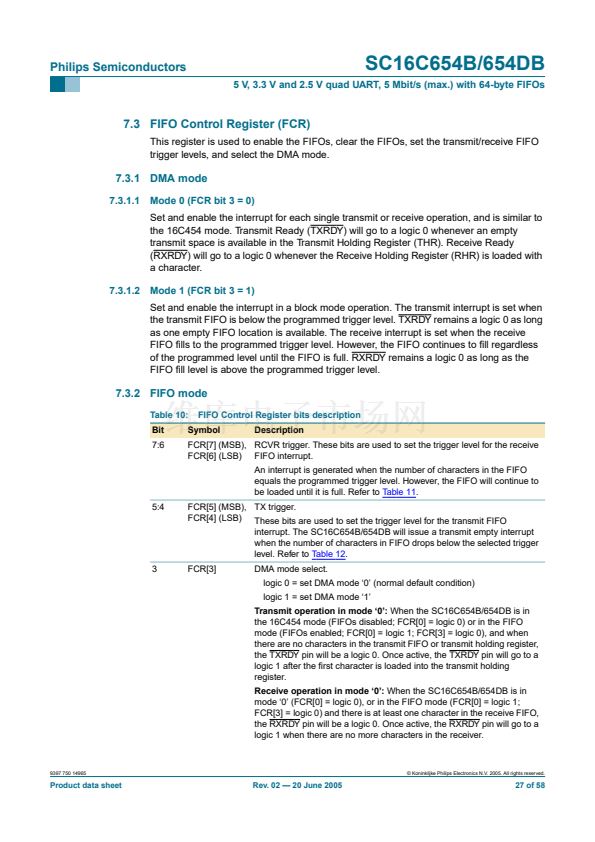
7.3 FIFO Control Register (FCR)
This register is used to enable the FIFOs, clear the FIFOs, set the transmit/receive FIFO
trigger levels, and select the DMA mode.
7.3.1 DMA mode
7.3.1.1
Mode 0 (FCR bit 3 = 0)
Set and enable the interrupt for each single transmit or receive operation, and is similar to
the 16C454 mode. Transmit Ready (TXRDY) will go to a logic 0 whenever an empty
transmit space is available in the Transmit Holding Register (THR). Receive Ready
(RXRDY) will go to a logic 0 whenever the Receive Holding Register (RHR) is loaded with
a character.
7.3.1.2
Mode 1 (FCR bit 3 = 1)
Set and enable the interrupt in a block mode operation. The transmit interrupt is set when
the transmit FIFO is below the programmed trigger level. TXRDY remains a logic 0 as long
as one empty FIFO location is available. The receive interrupt is set when the receive
FIFO 铿乴ls to the programmed trigger level. However, the FIFO continues to 铿乴l regardless
of the programmed level until the FIFO is full. RXRDY remains a logic 0 as long as the
FIFO 铿乴l level is above the programmed trigger level.
7.3.2 FIFO mode
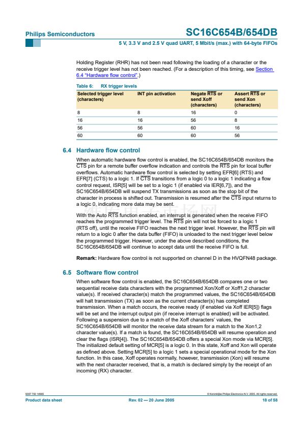
Table 10:
Bit
7:6
FIFO Control Register bits description
Description
Symbol
FCR[7] (MSB), RCVR trigger. These bits are used to set the trigger level for the receive
FCR[6] (LSB) FIFO interrupt.
An interrupt is generated when the number of characters in the FIFO
equals the programmed trigger level. However, the FIFO will continue to
be loaded until it is full. Refer to
Table 11.
5:4
FCR[5] (MSB), TX trigger.
FCR[4] (LSB) These bits are used to set the trigger level for the transmit FIFO
interrupt. The SC16C654B/654DB will issue a transmit empty interrupt
when the number of characters in FIFO drops below the selected trigger
level. Refer to
Table 12.
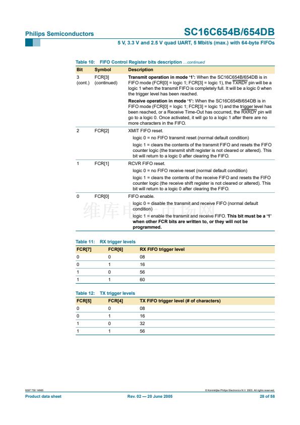
FCR[3]
DMA mode select.
logic 0 = set DMA mode 鈥?鈥?(normal default condition)
logic 1 = set DMA mode 鈥?鈥?/div>
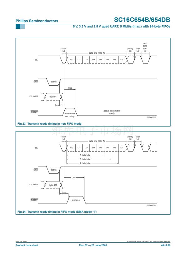
Transmit operation in mode 鈥?鈥?
When the SC16C654B/654DB is in
the 16C454 mode (FIFOs disabled; FCR[0] = logic 0) or in the FIFO
mode (FIFOs enabled; FCR[0] = logic 1; FCR[3] = logic 0), and when
there are no characters in the transmit FIFO or transmit holding register,
the TXRDY pin will be a logic 0. Once active, the TXRDY pin will go to a
logic 1 after the 铿乺st character is loaded into the transmit holding
register.
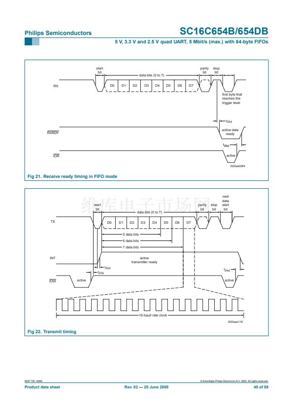
Receive operation in mode 鈥?鈥?
When the SC16C654B/654DB is in
mode 鈥?鈥?(FCR[0] = logic 0), or in the FIFO mode (FCR[0] = logic 1;
FCR[3] = logic 0) and there is at least one character in the receive FIFO,
the RXRDY pin will be a logic 0. Once active, the RXRDY pin will go to a
logic 1 when there are no more characters in the receiver.
3
9397 750 14965
漏 Koninklijke Philips Electronics N.V. 2005. All rights reserved.
Product data sheet
Rev. 02 鈥?20 June 2005
27 of 58


 1
1
 2
2
 3
3
 4
4
 5
5
 6
6
 7
7
 8
8
 9
9
 10
10
 11
11
 12
12
 13
13
 14
14
 15
15
 16
16
 17
17
 18
18
 19
19
 20
20
 21
21
 22
22
 23
23
 24
24
 25
25
 26
26
 27
27
 28
28
 29
29
 30
30
 31
31
 32
32
 33
33
 34
34
 35
35
 36
36
 37
37
 38
38
 39
39
 40
40
 41
41
 42
42
 43
43
 44
44
 45
45
 46
46
 47
47
 48
48
 49
49
 50
50
 51
51
 52
52
 53
53
 54
54
 55
55
 56
56
 57
57
 58
58
