Philips Semiconductors
SC16C654B/654DB
5 V, 3.3 V and 2.5 V quad UART, 5 Mbit/s (max.) with 64-byte FIFOs
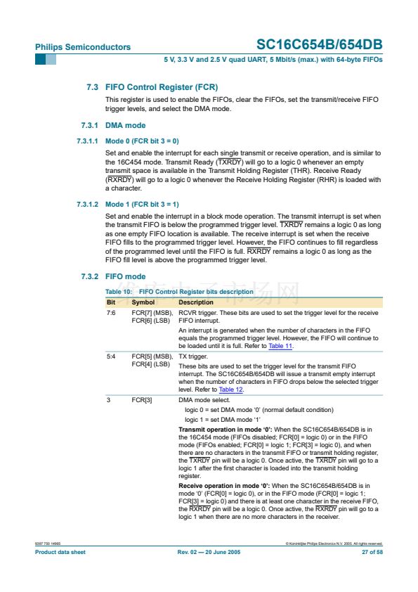
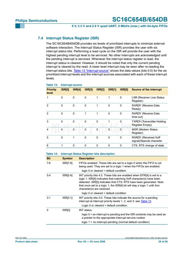
7.4 Interrupt Status Register (ISR)
The SC16C654B/654DB provides six levels of prioritized interrupts to minimize external
software interaction. The Interrupt Status Register (ISR) provides the user with six
interrupt status bits. Performing a read cycle on the ISR will provide the user with the
highest pending interrupt level to be serviced. No other interrupts are acknowledged until
the pending interrupt is serviced. Whenever the interrupt status register is read, the
interrupt status is cleared. However, it should be noted that only the current pending
interrupt is cleared by the read. A lower level interrupt may be seen after re-reading the
interrupt status bits.
Table 13 鈥淚nterrupt source鈥?/span>
shows the data values (bits 0:5) for the six
prioritized interrupt levels and the interrupt sources associated with each of these interrupt
levels.
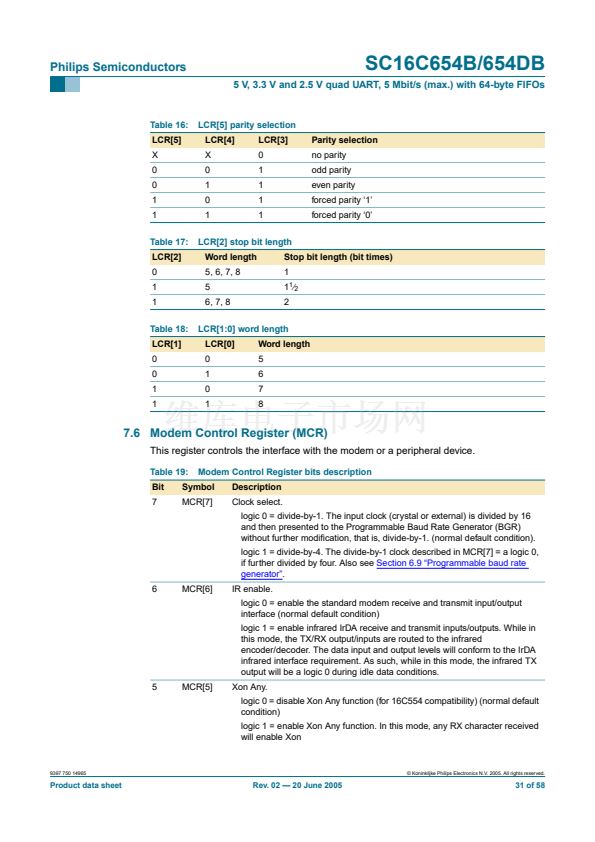
Table 13:
Priority
level
1
2
2
3
4
5
6
Table 14:
Bit
7:6
Interrupt source
ISR[5]
0
0
0
0
0
0
1
ISR[4]
0
0
0
0
0
1
0
ISR[3]
0
0
1
0
0
0
0
ISR[2]
1
1
1
0
0
0
0
ISR[1]
1
0
0
1
0
0
0
ISR[0]
0
0
0
0
0
0
0
Source of the interrupt
LSR (Receiver Line Status
Register)
RXRDY (Receive Data
Ready)
RXRDY (Receive Data
time-out)
TXRDY (Transmitter Holding
Register Empty)
MSR (Modem Status
Register)
RXRDY (Received Xoff
signal)/Special character
CTS, RTS change of state
Interrupt Status Register bits description
Symbol
ISR[7:6]
Description
FIFOs enabled. These bits are set to a logic 0 when the FIFO is not
being used. They are set to a logic 1 when the FIFOs are enabled.
logic 0 or cleared = default condition
INT priority bits 4:3. These bits are enabled when EFR[4] is set to a
logic 1. ISR[4] indicates that matching Xoff character(s) have been
detected. ISR[5] indicates that CTS, RTS have been generated. Note
that once set to a logic 1, the ISR[4] bit will stay a logic 1 until Xon
character(s) are received.
logic 0 or cleared = default condition
INT priority bits 2:0. These bits indicate the source for a pending
interrupt at interrupt priority levels 1, 2, and 3; see
Table 13.
Logic 0 or cleared = default condition.
INT status.
logic 0 = an interrupt is pending and the ISR contents may be used as
a pointer to the appropriate interrupt service routine
logic 1 = no interrupt pending (normal default condition)
5:4
ISR[5:4]
3:1
ISR[3:1]
0
ISR[0]
9397 750 14965
漏 Koninklijke Philips Electronics N.V. 2005. All rights reserved.
Product data sheet
Rev. 02 鈥?20 June 2005
29 of 58


 1
1
 2
2
 3
3
 4
4
 5
5
 6
6
 7
7
 8
8
 9
9
 10
10
 11
11
 12
12
 13
13
 14
14
 15
15
 16
16
 17
17
 18
18
 19
19
 20
20
 21
21
 22
22
 23
23
 24
24
 25
25
 26
26
 27
27
 28
28
 29
29
 30
30
 31
31
 32
32
 33
33
 34
34
 35
35
 36
36
 37
37
 38
38
 39
39
 40
40
 41
41
 42
42
 43
43
 44
44
 45
45
 46
46
 47
47
 48
48
 49
49
 50
50
 51
51
 52
52
 53
53
 54
54
 55
55
 56
56
 57
57
 58
58
