ISL9203
Theory of Operation
The ISL9203 is an integrated charger for single-cell Li-ion or
Li-polymer batteries. The ISL9203 functions as a traditional
linear charger when powered with a voltage-source adapter.
When powered with a current-limited adapter, the charger
minimizes the thermal dissipation commonly seen in
traditional linear chargers.
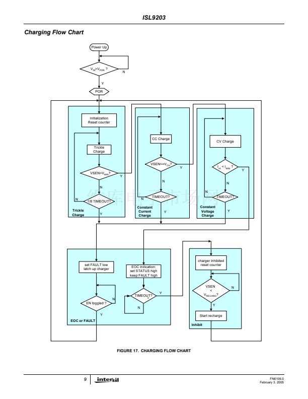
As a linear charger, the ISL9203 charges a battery in the
popular constant current (CC) and constant voltage (CV)
profile. The constant charge current I
REF
is programmable
up to 1.5A with an external resistor. The charge voltage V
CH
has 1% accuracy over the entire recommended operating
condition range. The charger always preconditions the
battery with 10% of the programmed current at the beginning
of a charge cycle, until the battery voltage is verified to be
above the minimum fast charge voltage, V
MIN
. This low-
current preconditioning charge mode is named trickle mode.
The verification takes 15 cycles of an internal oscillator
whose period is programmable with the timing capacitor. A
thermal-foldback feature removes the thermal concern
typically seen in linear chargers. The charger reduces the
charge current automatically as the IC internal temperature
rises above 100掳C to prevent further temperature rise. The
thermal-foldback feature guarantees safe operation when
the printed circuit board (PCB) is space limited for thermal
dissipation.
The charger offers a safety timer for setting the fast charge
time (TIMEOUT) limit to prevent charging a dead battery for
an extensively long time. The trickle mode is limited to 1/8 of
TIMEOUT.
The charger automatically re-charges the battery when the
battery voltage drops below a recharge threshold. When the
wall adapter is not present, the ISL9203 draws less than 1
碌
A
current from the battery.
Trickle
Mode
Constant Current
Mode
Constant Voltage
Mode
Inhibit
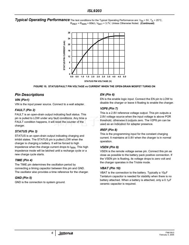
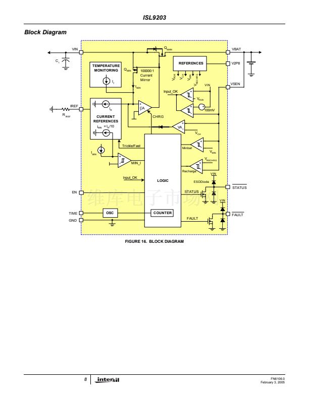
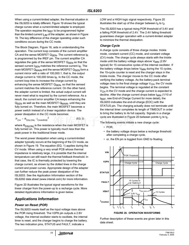
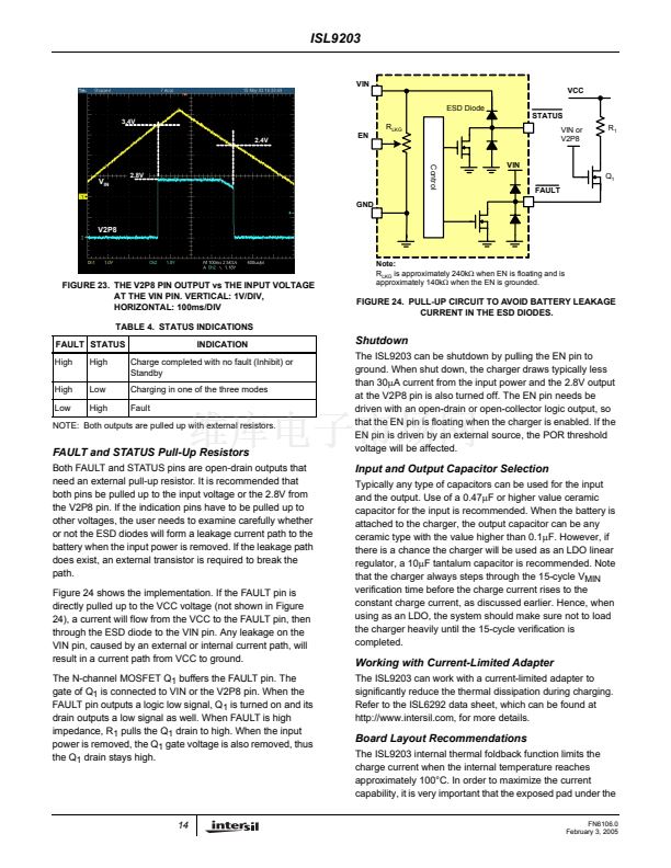
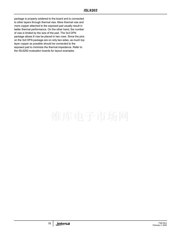
Three indication pins are available from the charger to
indicate the charge status. The V2P8 outputs a 2.8V dc
voltage when the input voltage is above the power-on reset
(POR) level and can be used as the power-present
indication. This pin is capable of sourcing a 2mA current, so
it can also be used to bias external circuits.
The STATUS pin is an open-drain logic output that turns
LOW at the beginning of a charge cycle until the end-of-
charge (EOC) condition is qualified. The EOC condition is:
the battery voltage rises above the recharge threshold and
the charge current falls below a user-programmable EOC
current threshold. Once the EOC condition is qualified, the
STATUS output rises to HIGH and is latched. The latch is
released at the beginning of a charge or re-charge cycle.
The open-drain FAULT pin turns low when a charge time
fault occurs or when the IREF pin is pulled below 0.35V or
above 1.4V.
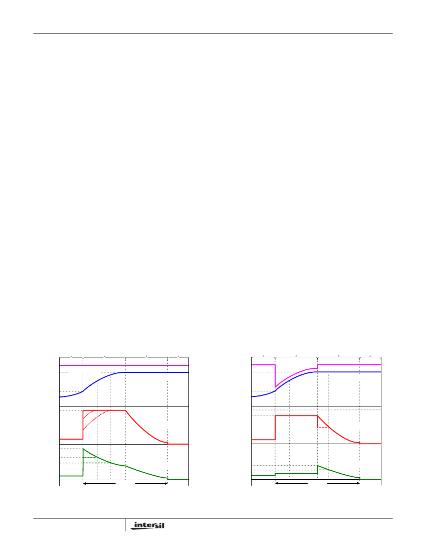
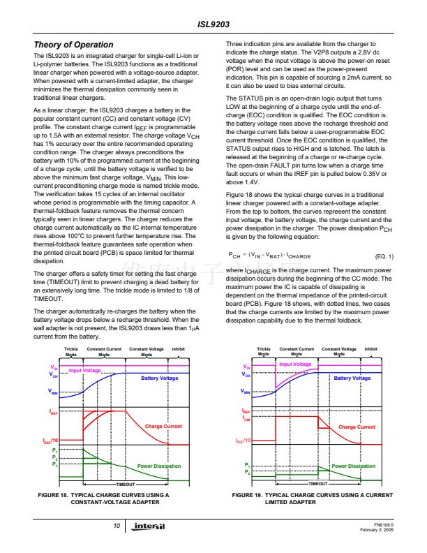
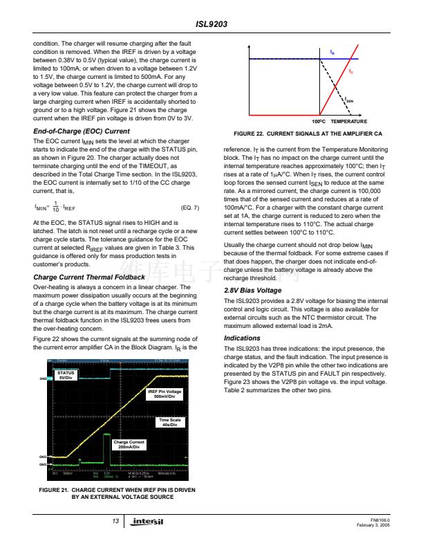
Figure 18 shows the typical charge curves in a traditional
linear charger powered with a constant-voltage adapter.
From the top to bottom, the curves represent the constant
input voltage, the battery voltage, the charge current and the
power dissipation in the charger. The power dissipation P
CH
is given by the following equation:
P
CH
=
(
V
IN
鈥?/div>
V
BAT
) 鈰?/div>
I
CHARGE
(EQ. 1)
where I
CHARGE
is the charge current. The maximum power
dissipation occurs during the beginning of the CC mode. The
maximum power the IC is capable of dissipating is
dependent on the thermal impedance of the printed-circuit
board (PCB). Figure 18 shows, with dotted lines, two cases
that the charge currents are limited by the maximum power
dissipation capability due to the thermal foldback.
Trickle
Mode
Constant Current
Mode
Constant Voltage
Mode
Inhibit
V
IN
V
CH
V
MIN
Input Voltage
Battery Voltage
V
IN
V
CH
V
MIN
I
REF
I
LIM
Input Voltage
Battery Voltage
I
REF
Charge Current
I
REF
/10
P
1
P
2
P
3
Power Dissipation
Charge Current
I
REF
/10
P
1
P
2
TIMEOUT
Power Dissipation
TIMEOUT
FIGURE 18. TYPICAL CHARGE CURVES USING A
CONSTANT-VOLTAGE ADAPTER
FIGURE 19. TYPICAL CHARGE CURVES USING A CURRENT-
LIMITED ADAPTER
10
FN6106.0
February 3, 2005


 1
1
 2
2
 3
3
 4
4
 5
5
 6
6
 7
7
 8
8
 9
9
 10
10
 11
11
 12
12
 13
13
 14
14
 15
15
 16
16
