ISL9203
Typical Operating Performance
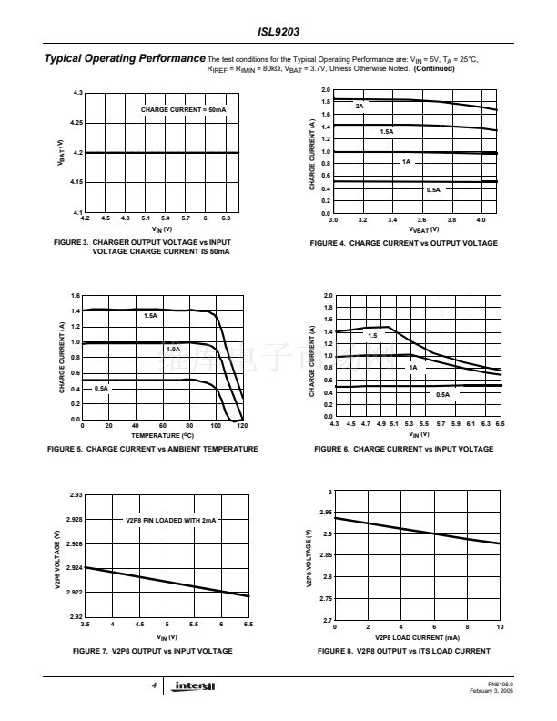
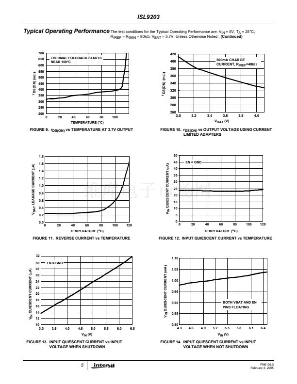
The test conditions for the Typical Operating Performance are: V
IN
= 5V, T
A
= 25掳C,
R
IREF
= R
IMIN
= 80k鈩? V
BAT
= 3.7V, Unless Otherwise Noted.
(Continued)
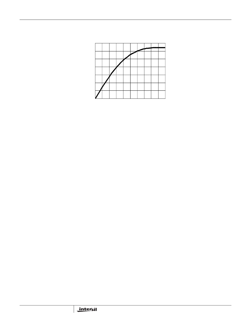
28
24
STATUS PIN CURRENT (mA)
20
16
12
8
4
0
0.0
0.5
1.0
1.5
2.0
2.5
3.0
3.5
4.0
4.5
5.0
STATUS PIN VOLTAGE (V)
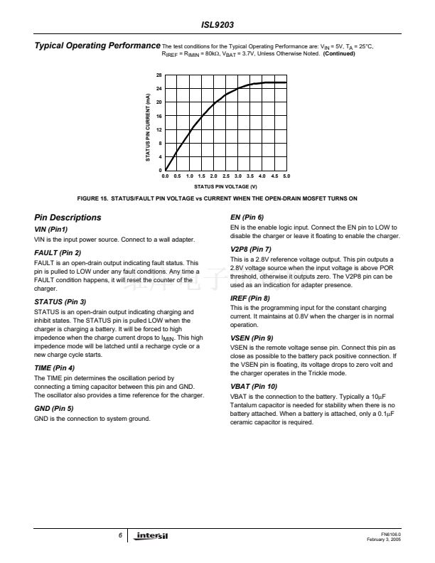
FIGURE 15. STATUS/FAULT PIN VOLTAGE vs CURRENT WHEN THE OPEN-DRAIN MOSFET TURNS ON
Pin Descriptions
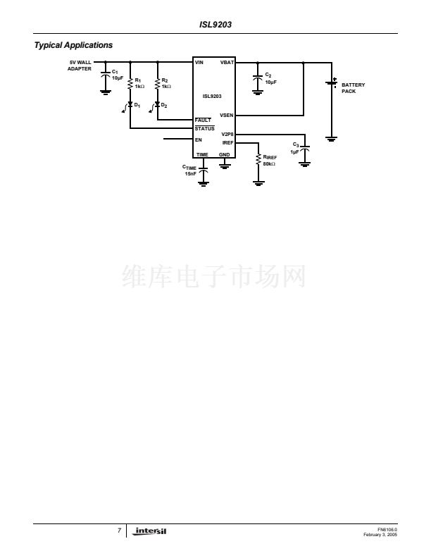
VIN (Pin1)
VIN is the input power source. Connect to a wall adapter.
EN (Pin 6)
EN is the enable logic input. Connect the EN pin to LOW to
disable the charger or leave it floating to enable the charger.
FAULT (Pin 2)
FAULT is an open-drain output indicating fault status. This
pin is pulled to LOW under any fault conditions. Any time a
FAULT condition happens, it will reset the counter of the
charger.
V2P8 (Pin 7)
This is a 2.8V reference voltage output. This pin outputs a
2.8V voltage source when the input voltage is above POR
threshold, otherwise it outputs zero. The V2P8 pin can be
used as an indication for adapter presence.
STATUS (Pin 3)
STATUS is an open-drain output indicating charging and
inhibit states. The STATUS pin is pulled LOW when the
charger is charging a battery. It will be forced to high
impedence when the charge current drops to I
MIN
. This high
impedence mode will be latched until a recharge cycle or a
new charge cycle starts.
IREF (Pin 8)
This is the programming input for the constant charging
current. It maintains at 0.8V when the charger is in normal
operation.
VSEN (Pin 9)
VSEN is the remote voltage sense pin. Connect this pin as
close as possible to the battery pack positive connection. If
the VSEN pin is floating, its voltage drops to zero volt and
the charger operates in the Trickle mode.
TIME (Pin 4)
The TIME pin determines the oscillation period by
connecting a timing capacitor between this pin and GND.
The oscillator also provides a time reference for the charger.
VBAT (Pin 10)
VBAT is the connection to the battery. Typically a 10碌F
Tantalum capacitor is needed for stability when there is no
battery attached. When a battery is attached, only a 0.1碌F
ceramic capacitor is required.
GND (Pin 5)
GND is the connection to system ground.
6
FN6106.0
February 3, 2005


 1
1
 2
2
 3
3
 4
4
 5
5
 6
6
 7
7
 8
8
 9
9
 10
10
 11
11
 12
12
 13
13
 14
14
 15
15
 16
16
