ISL9203
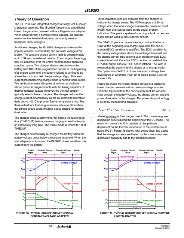
When using a current-limited adapter, the thermal situation in
the ISL9203 is totally different. Figure 19 shows the typical
charge curves when a current-limited adapter is employed.
The operation requires the I
REF
to be programmed higher
than the limited current I
LIM
of the adapter, as shown in Figure
19. The key difference of the charger operating under such
conditions occurs during the CC mode.
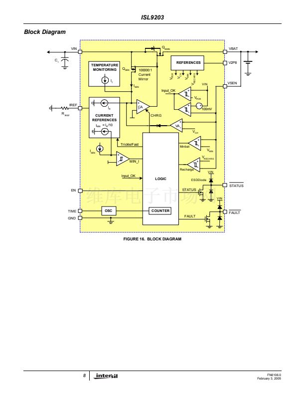
The Block Diagram, Figure 16, aids in understanding the
operation. The current loop consists of the current amplifier
CA and the sense MOSFET Q
SEN
. The current reference I
R
is programmed by the IREF pin. The current amplifier CA
regulates the gate of the sense MOSFET Q
SEN
so that the
sensed current I
SEN
matches the reference current I
R
. The
main MOSFET Q
MAIN
and the sense MOSFET Q
SEN
form a
current mirror with a ratio of 100,000:1, that is, the output
charge current is 100,000 times I
R
. In the CC mode, the
current loop tries to increase the charge current by
enhancing the sense MOSFET Q
SEN
, so that the sensed
current matches the reference current. On the other hand,
the adapter current is limited, the actual output current will
never meet what is required by the current reference. As a
result, the current error amplifier CA keeps enhancing the
Q
SEN
as well as the main MOSFET Q
MAIN
, until they are
fully turned on. Therefore, the main MOSFET becomes a
power switch instead of a linear regulation device. The
power dissipation in the CC mode becomes:
P
CH
=
R
DS
(
ON
)
鈰?/div>
I
CHARGE
2
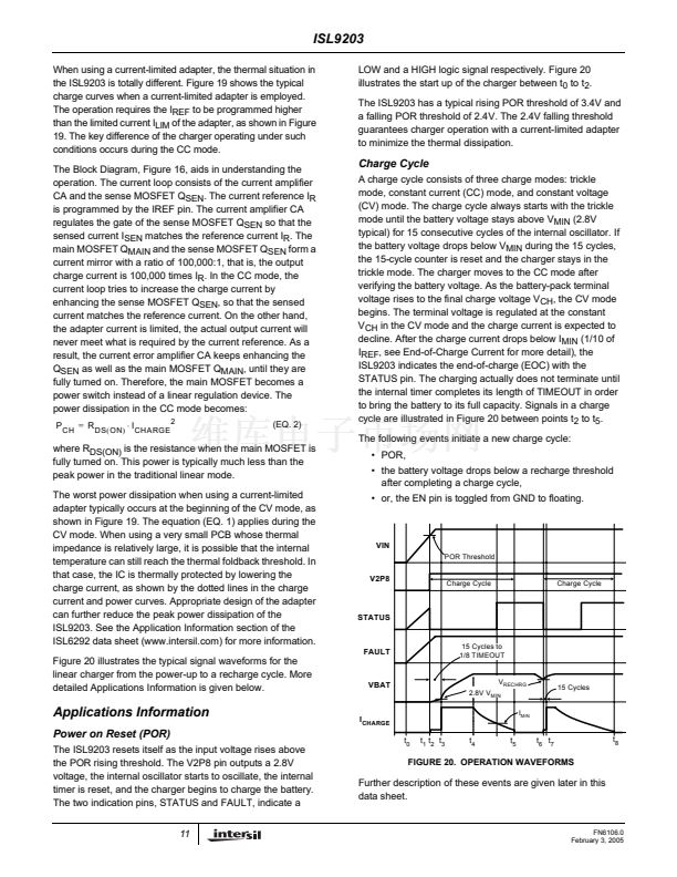
LOW and a HIGH logic signal respectively. Figure 20
illustrates the start up of the charger between t
0
to t
2
.
The ISL9203 has a typical rising POR threshold of 3.4V and
a falling POR threshold of 2.4V. The 2.4V falling threshold
guarantees charger operation with a current-limited adapter
to minimize the thermal dissipation.
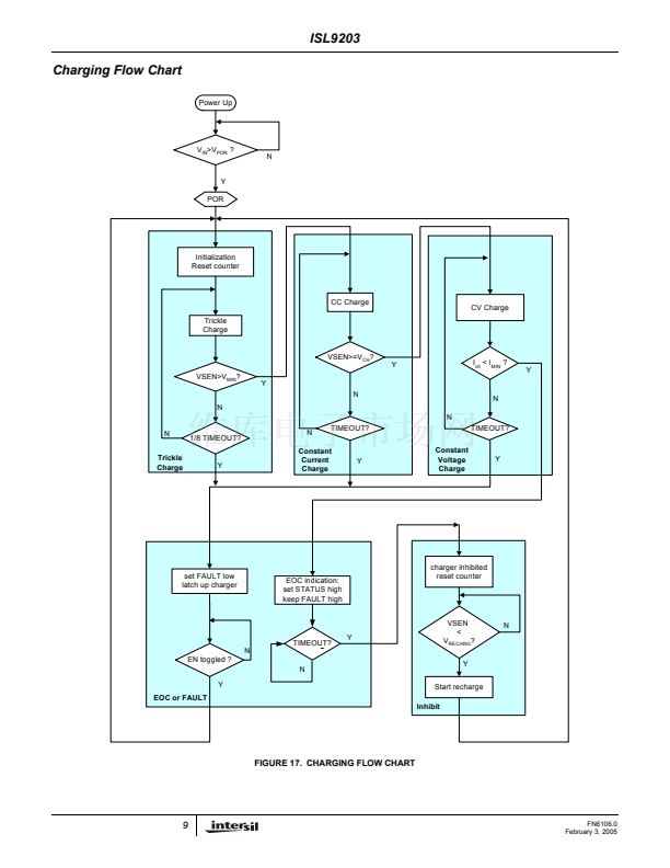
Charge Cycle
A charge cycle consists of three charge modes: trickle
mode, constant current (CC) mode, and constant voltage
(CV) mode. The charge cycle always starts with the trickle
mode until the battery voltage stays above V
MIN
(2.8V
typical) for 15 consecutive cycles of the internal oscillator. If
the battery voltage drops below V
MIN
during the 15 cycles,
the 15-cycle counter is reset and the charger stays in the
trickle mode. The charger moves to the CC mode after
verifying the battery voltage. As the battery-pack terminal
voltage rises to the final charge voltage V
CH
, the CV mode
begins. The terminal voltage is regulated at the constant
V
CH
in the CV mode and the charge current is expected to
decline. After the charge current drops below I
MIN
(1/10 of
I
REF
, see End-of-Charge Current for more detail), the
ISL9203 indicates the end-of-charge (EOC) with the
STATUS pin. The charging actually does not terminate until
the internal timer completes its length of TIMEOUT in order
to bring the battery to its full capacity. Signals in a charge
cycle are illustrated in Figure 20 between points t
2
to t
5
.
The following events initiate a new charge cycle:
(EQ. 2)
where R
DS(ON)
is the resistance when the main MOSFET is
fully turned on. This power is typically much less than the
peak power in the traditional linear mode.
The worst power dissipation when using a current-limited
adapter typically occurs at the beginning of the CV mode, as
shown in Figure 19. The equation (EQ. 1) applies during the
CV mode. When using a very small PCB whose thermal
impedance is relatively large, it is possible that the internal
temperature can still reach the thermal foldback threshold. In
that case, the IC is thermally protected by lowering the
charge current, as shown by the dotted lines in the charge
current and power curves. Appropriate design of the adapter
can further reduce the peak power dissipation of the
ISL9203. See the Application Information section of the
ISL6292 data sheet (www.intersil.com) for more information.
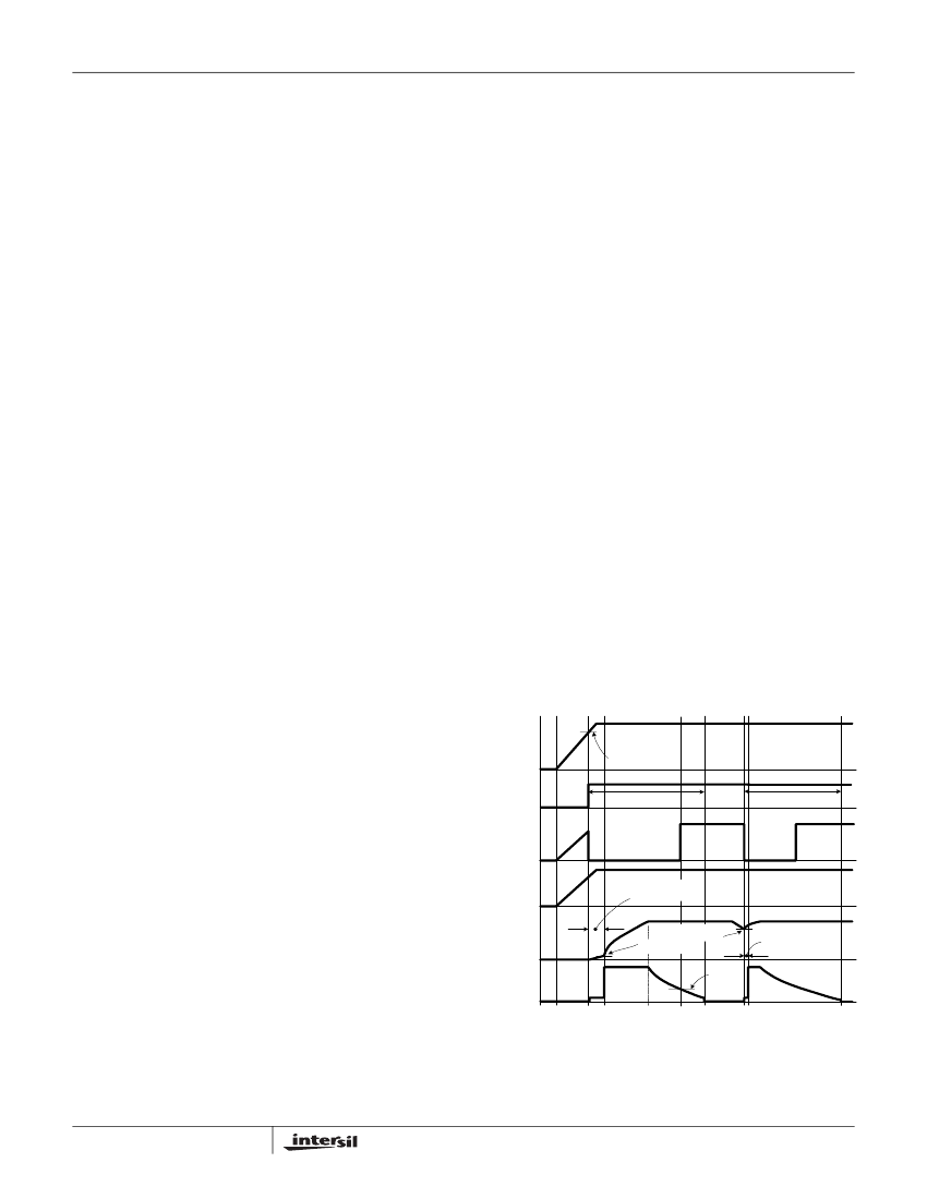
Figure 20 illustrates the typical signal waveforms for the
linear charger from the power-up to a recharge cycle. More
detailed Applications Information is given below.
鈥?POR,
鈥?the battery voltage drops below a recharge threshold
after completing a charge cycle,
鈥?or, the EN pin is toggled from GND to floating.
VIN
POR Threshold
V2P8
Charge Cycle
Charge Cycle
STATUS
FAULT
15 Cycles to
1/8 TIMEOUT
VBAT
V
RECHRG
2.8V V
MIN
I
MIN
15 Cycles
Applications Information
Power on Reset (POR)
The ISL9203 resets itself as the input voltage rises above
the POR rising threshold. The V2P8 pin outputs a 2.8V
voltage, the internal oscillator starts to oscillate, the internal
timer is reset, and the charger begins to charge the battery.
The two indication pins, STATUS and FAULT, indicate a
11
I
CHARGE
t
0
t
1
t
2
t
3
t
4
t
5
t
6
t
7
t
8
FIGURE 20. OPERATION WAVEFORMS
Further description of these events are given later in this
data sheet.
FN6106.0
February 3, 2005


 1
1
 2
2
 3
3
 4
4
 5
5
 6
6
 7
7
 8
8
 9
9
 10
10
 11
11
 12
12
 13
13
 14
14
 15
15
 16
16
