Philips Semiconductors
SC16C754B
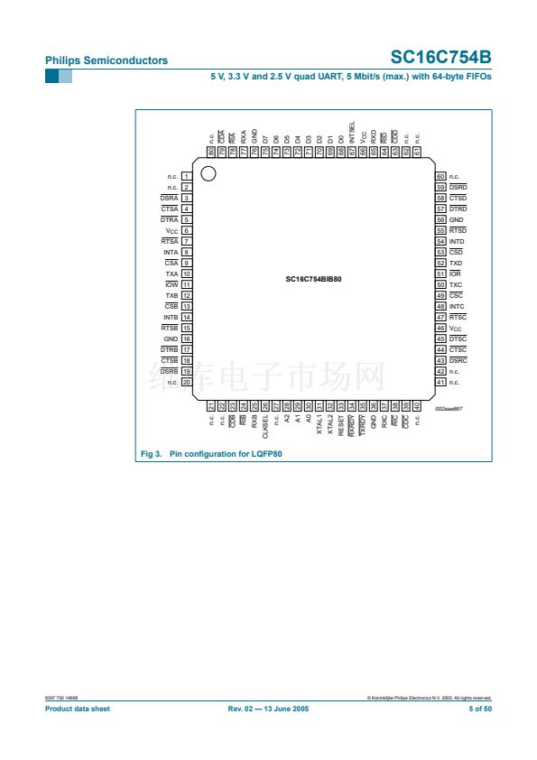
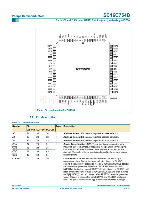
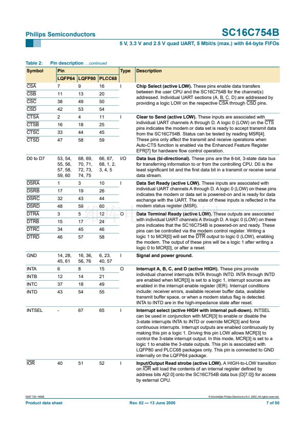
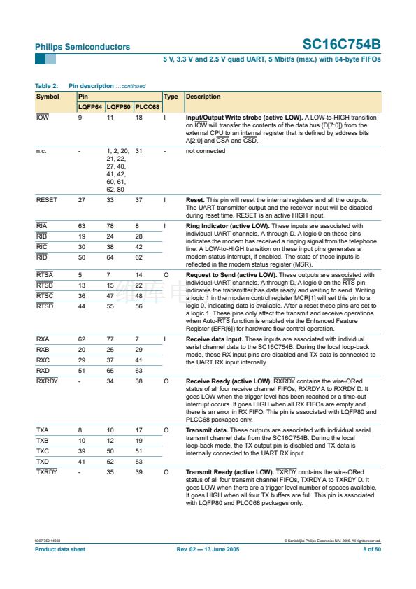
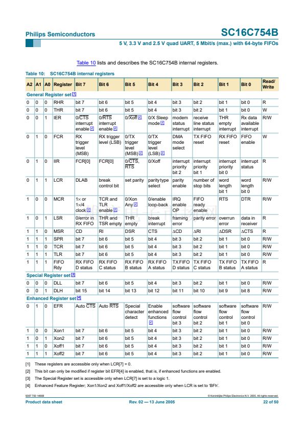
5 V, 3.3 V and 2.5 V quad UART, 5 Mbit/s (max.) with 64-byte FIFOs
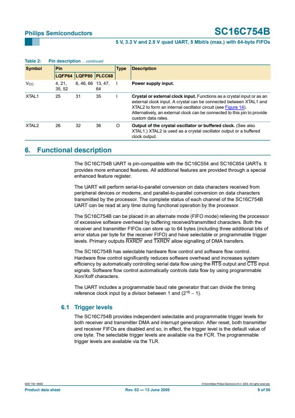
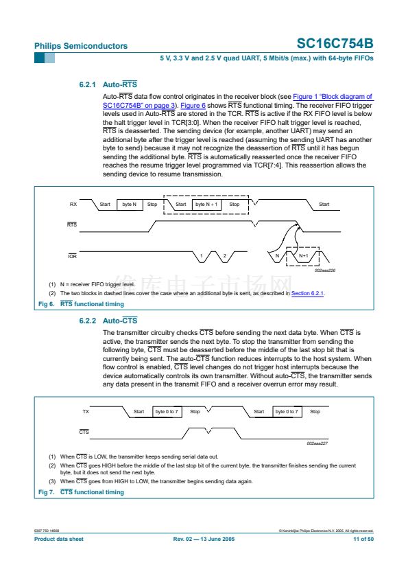
6.2.1 Auto-RTS
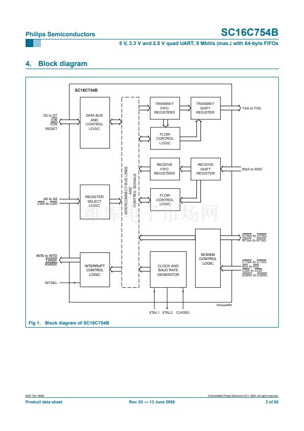
Auto-RTS data 铿俹w control originates in the receiver block (see
Figure 1 鈥淏lock diagram of
SC16C754B鈥?on page 3). Figure 6
shows RTS functional timing. The receiver FIFO trigger
levels used in Auto-RTS are stored in the TCR. RTS is active if the RX FIFO level is below
the halt trigger level in TCR[3:0]. When the receiver FIFO halt trigger level is reached,
RTS is deasserted. The sending device (for example, another UART) may send an
additional byte after the trigger level is reached (assuming the sending UART has another
byte to send) because it may not recognize the deassertion of RTS until it has begun
sending the additional byte. RTS is automatically reasserted once the receiver FIFO
reaches the resume trigger level programmed via TCR[7:4]. This reassertion allows the
sending device to resume transmission.
RX
Start
byte N
Stop
Start
byte N
+
1
Stop
Start
RTS
IOR
1
2
N
N+1
002aaa226
(1) N = receiver FIFO trigger level.
(2) The two blocks in dashed lines cover the case where an additional byte is sent, as described in
Section 6.2.1.
Fig 6. RTS functional timing
6.2.2 Auto-CTS
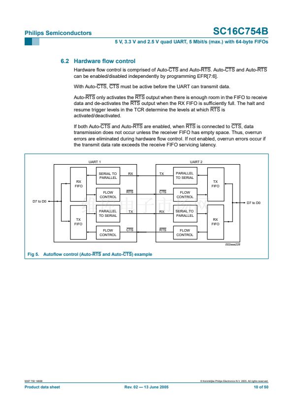
The transmitter circuitry checks CTS before sending the next data byte. When CTS is
active, the transmitter sends the next byte. To stop the transmitter from sending the
following byte, CTS must be deasserted before the middle of the last stop bit that is
currently being sent. The auto-CTS function reduces interrupts to the host system. When
铿俹w control is enabled, CTS level changes do not trigger host interrupts because the
device automatically controls its own transmitter. Without auto-CTS, the transmitter sends
any data present in the transmit FIFO and a receiver overrun error may result.
TX
Start
byte 0 to 7
Stop
Start
byte 0 to 7
Stop
CTS
002aaa227
(1) When CTS is LOW, the transmitter keeps sending serial data out.
(2) When CTS goes HIGH before the middle of the last stop bit of the current byte, the transmitter 铿乶ishes sending the current
byte, but it does not send the next byte.
(3) When CTS goes from HIGH to LOW, the transmitter begins sending data again.
Fig 7. CTS functional timing
9397 750 14668
漏 Koninklijke Philips Electronics N.V. 2005. All rights reserved.
Product data sheet
Rev. 02 鈥?13 June 2005
11 of 50


 1
1
 2
2
 3
3
 4
4
 5
5
 6
6
 7
7
 8
8
 9
9
 10
10
 11
11
 12
12
 13
13
 14
14
 15
15
 16
16
 17
17
 18
18
 19
19
 20
20
 21
21
 22
22
 23
23
 24
24
 25
25
 26
26
 27
27
 28
28
 29
29
 30
30
 31
31
 32
32
 33
33
 34
34
 35
35
 36
36
 37
37
 38
38
 39
39
 40
40
 41
41
 42
42
 43
43
 44
44
 45
45
 46
46
 47
47
 48
48
 49
49
 50
50
