Philips Semiconductors
SC16C754B
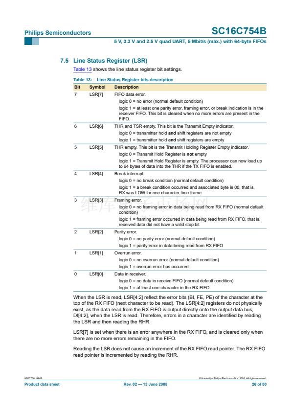
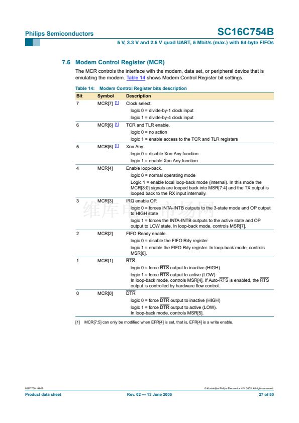
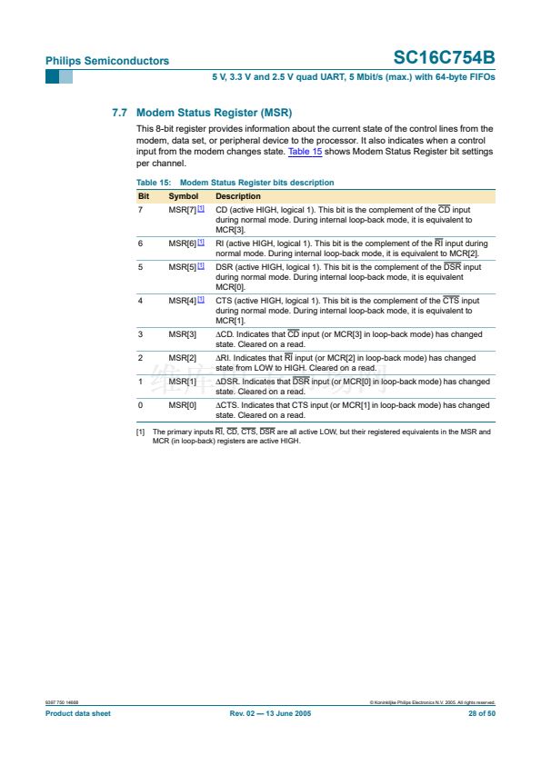
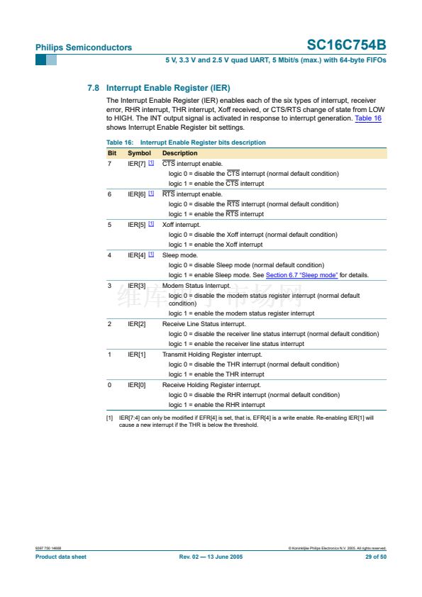
5 V, 3.3 V and 2.5 V quad UART, 5 Mbit/s (max.) with 64-byte FIFOs
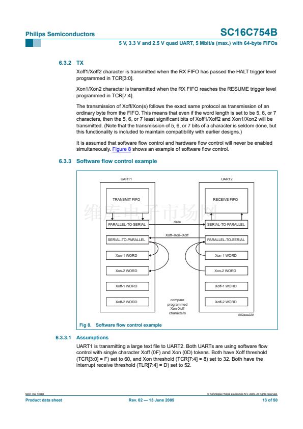
UART1 begins transmission and sends 52 characters, at which point UART2 will generate
an interrupt to its processor to service the RCV FIFO, but assumes the interrupt latency is
fairly long. UART1 will continue sending characters until a total of 60 characters have
been sent. At this time, UART2 will transmit a 0F to UART1, informing UART1 to halt
transmission. UART1 will likely send the 61
st
character while UART2 is sending the Xoff
character. Now UART2 is serviced and the processor reads enough data out of the RX
FIFO that the level drops to 32. UART2 will now send a 0D to UART1, informing UART1 to
resume transmission.
6.4 Reset
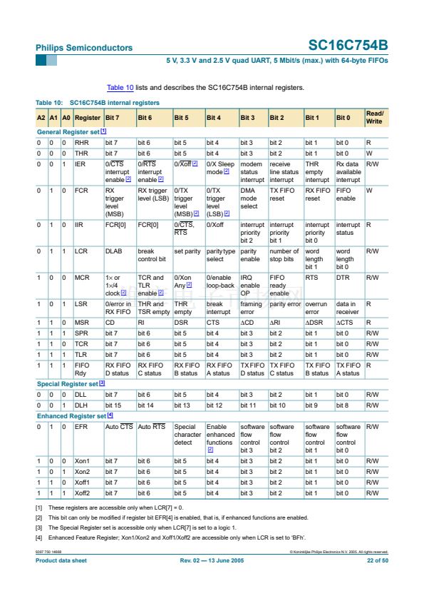
Table 4
summarizes the state of register after reset.
Table 4:
Register
Interrupt enable register
Interrupt identi铿乧ation register
FIFO control register
Line control register
Modem control register
Line status register
Modem status register
Enhanced feature register
Receiver holding register
Transmitter holding register
Transmission control register
Trigger level register
Register reset functions
Reset control
RESET
RESET
RESET
RESET
RESET
RESET
RESET
RESET
RESET
RESET
RESET
RESET
Reset state
all bits cleared
bit 0 is set; all other bits cleared
all bits cleared
reset to 0001 1101 (1Dh)
all bits cleared
bit 5 and bit 6 set; all other bits cleared
bits 3:0 cleared; bits 7:4 input signals
all bits cleared
pointer logic cleared
pointer logic cleared
all bits cleared
all bits cleared
Remark:
Registers DLL, DLH, SPR, Xon1, Xon2, Xoff1, Xoff2 are not reset by the
top-level reset signal RESET, that is, they hold their initialization values during reset.
Table 5
summarizes the state of registers after reset.
Table 5:
Signal
TX
RTS
DTR
RXRDY
TXRDY
Signal RESET functions
Reset control
RESET
RESET
RESET
RESET
RESET
Reset state
HIGH
HIGH
HIGH
HIGH
LOW
9397 750 14668
漏 Koninklijke Philips Electronics N.V. 2005. All rights reserved.
Product data sheet
Rev. 02 鈥?13 June 2005
14 of 50


 1
1
 2
2
 3
3
 4
4
 5
5
 6
6
 7
7
 8
8
 9
9
 10
10
 11
11
 12
12
 13
13
 14
14
 15
15
 16
16
 17
17
 18
18
 19
19
 20
20
 21
21
 22
22
 23
23
 24
24
 25
25
 26
26
 27
27
 28
28
 29
29
 30
30
 31
31
 32
32
 33
33
 34
34
 35
35
 36
36
 37
37
 38
38
 39
39
 40
40
 41
41
 42
42
 43
43
 44
44
 45
45
 46
46
 47
47
 48
48
 49
49
 50
50
