铮?/div>
prescaler
divisor =
--------------------------------------------------------------------------------
-
(
desired baud rate
脳
16
)
Where:
prescaler = 1, when MCR[7] is set to 0 after reset (divide-by-1 clock selected)
prescaler = 4, when MCR[7] is set to 1 after reset (divide-by-4 clock selected).
Remark:
The default value of prescaler after reset is divide-by-1.
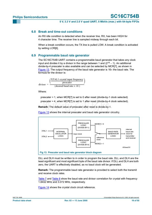
Figure 13
shows the internal prescaler and baud rate generator circuitry.
PRESCALER
LOGIC
(DIVIDE-BY-1)
XTAL1
XTAL2
INTERNAL
OSCILLATOR
LOGIC
MCR[7] = 0
internal
baud rate
clock for
transmitter
and receiver
input clock
reference
clock
MCR[7] = 1
BAUD RATE
GENERATOR
LOGIC
PRESCALER
LOGIC
(DIVIDE-BY-4)
002aaa233
Fig 13. Prescaler and baud rate generator block diagram
DLL and DLH must be written to in order to program the baud rate. DLL and DLH are the
least signi铿乧ant and most signi铿乧ant byte of the baud rate divisor. If DLL and DLH are both
zero, the UART is effectively disabled, as no baud clock will be generated.
Remark:
The programmable baud rate generator is provided to select both the transmit
and receive clock rates.
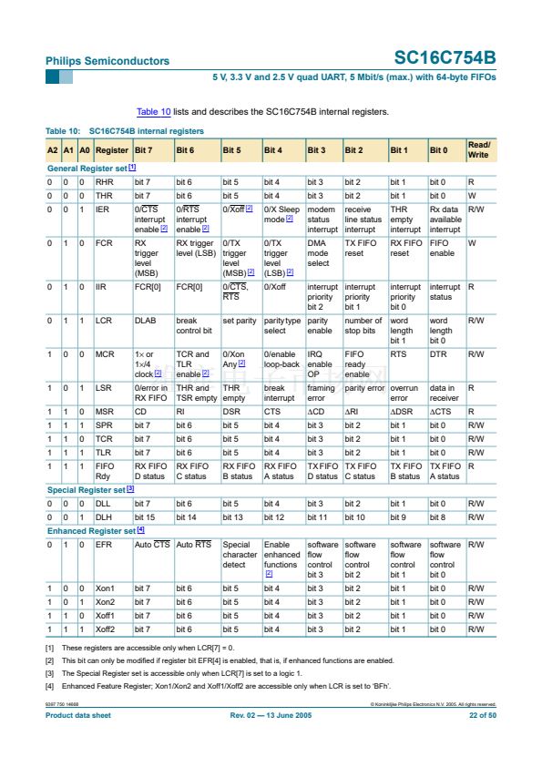
Table 7
and
Table 8
show the baud rate and divisor correlation for crystal with frequency
1.8432 MHz and 3.072 MHz, respectively.
Figure 14
shows the crystal clock circuit reference.
9397 750 14668
漏 Koninklijke Philips Electronics N.V. 2005. All rights reserved.
Product data sheet
Rev. 02 鈥?13 June 2005
19 of 50


 1
1
 2
2
 3
3
 4
4
 5
5
 6
6
 7
7
 8
8
 9
9
 10
10
 11
11
 12
12
 13
13
 14
14
 15
15
 16
16
 17
17
 18
18
 19
19
 20
20
 21
21
 22
22
 23
23
 24
24
 25
25
 26
26
 27
27
 28
28
 29
29
 30
30
 31
31
 32
32
 33
33
 34
34
 35
35
 36
36
 37
37
 38
38
 39
39
 40
40
 41
41
 42
42
 43
43
 44
44
 45
45
 46
46
 47
47
 48
48
 49
49
 50
50
