Philips Semiconductors
SC16C754B
5 V, 3.3 V and 2.5 V quad UART, 5 Mbit/s (max.) with 64-byte FIFOs
Remark:
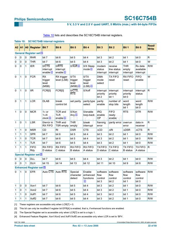
Refer to the notes under
Table 9
for more register access information.
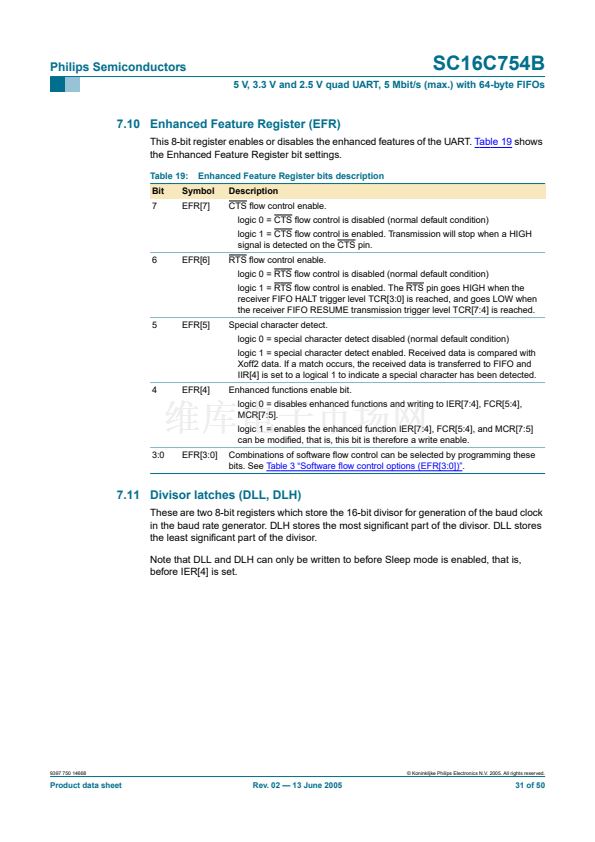
7.1 Receiver Holding Register (RHR)
The receiver section consists of the Receiver Holding Register (RHR) and the Receiver
Shift Register (RSR). The RHR is actually a 64-byte FIFO. The RSR receives serial data
from the RX terminal. The data is converted to parallel data and moved to the RHR. The
receiver section is controlled by the Line Control Register (LCR). If the FIFO is disabled,
location zero of the FIFO is used to store the characters.
Remark:
In this case, characters are overwritten if over铿俹w occurs.
If over铿俹w occurs, characters are lost. The RHR also stores the error status bits
associated with each character.
7.2 Transmit Holding Register (THR)
The transmitter section consists of the Transmit Holding Register (THR) and the Transmit
Shift Register (TSR). The THR is actually a 64-byte FIFO. The THR receives data and
shifts it into the TSR, where it is converted to serial data and moved out on the TX
terminal. If the FIFO is disabled, the FIFO is still used to store the byte. Characters are
lost if over铿俹w occurs.
9397 750 14668
漏 Koninklijke Philips Electronics N.V. 2005. All rights reserved.
Product data sheet
Rev. 02 鈥?13 June 2005
23 of 50


 1
1
 2
2
 3
3
 4
4
 5
5
 6
6
 7
7
 8
8
 9
9
 10
10
 11
11
 12
12
 13
13
 14
14
 15
15
 16
16
 17
17
 18
18
 19
19
 20
20
 21
21
 22
22
 23
23
 24
24
 25
25
 26
26
 27
27
 28
28
 29
29
 30
30
 31
31
 32
32
 33
33
 34
34
 35
35
 36
36
 37
37
 38
38
 39
39
 40
40
 41
41
 42
42
 43
43
 44
44
 45
45
 46
46
 47
47
 48
48
 49
49
 50
50
