Philips Semiconductors
SC16C754B
5 V, 3.3 V and 2.5 V quad UART, 5 Mbit/s (max.) with 64-byte FIFOs
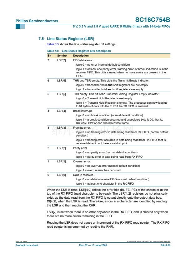
7.5 Line Status Register (LSR)
Table 13
shows the line status register bit settings.
Table 13:
Bit
7
Line Status Register bits description
Description
FIFO data error.
logic 0 = no error (normal default condition)
logic 1 = at least one parity error, framing error, or break indication is in the
receiver FIFO. This bit is cleared when no more errors are present in the
FIFO.
6
LSR[6]
THR and TSR empty. This bit is the Transmit Empty indicator.
logic 0 = transmitter hold
and
shift registers are not empty
logic 1 = transmitter hold
and
shift registers are empty
5
LSR[5]
THR empty. This bit is the Transmit Holding Register Empty indicator.
logic 0 = Transmit Hold Register is
not
empty
logic 1 = Transmit Hold Register is empty. The processor can now load up
to 64 bytes of data into the THR if the TX FIFO is enabled.
4
LSR[4]
Break interrupt.
logic 0 = no break condition (normal default condition)
logic 1 = a break condition occurred and associated byte is 00, that is,
RX was LOW for one character time frame
3
LSR[3]
Framing error.
logic 0 = no framing error in data being read from RX FIFO (normal default
condition)
logic 1 = framing error occurred in data being read from RX FIFO, that is,
received data did not have a valid stop bit
2
LSR[2]
Parity error.
logic 0 = no parity error (normal default condition)
logic 1 = parity error in data being read from RX FIFO
1
LSR[1]
Overrun error.
logic 0 = no overrun error (normal default condition)
logic 1 = overrun error has occurred
0
LSR[0]
Data in receiver.
logic 0 = no data in receive FIFO (normal default condition)
logic 1 = at least one character in the RX FIFO
Symbol
LSR[7]
When the LSR is read, LSR[4:2] re铿俥ct the error bits (BI, FE, PE) of the character at the
top of the RX FIFO (next character to be read). The LSR[4:2] registers do not physically
exist, as the data read from the RX FIFO is output directly onto the output data bus,
DI[4:2], when the LSR is read. Therefore, errors in a character are identi铿乪d by reading
the LSR and then reading the RHR.
LSR[7] is set when there is an error anywhere in the RX FIFO, and is cleared only when
there are no more errors remaining in the FIFO.
Reading the LSR does not cause an increment of the RX FIFO read pointer. The RX FIFO
read pointer is incremented by reading the RHR.
9397 750 14668
漏 Koninklijke Philips Electronics N.V. 2005. All rights reserved.
Product data sheet
Rev. 02 鈥?13 June 2005
26 of 50


 1
1
 2
2
 3
3
 4
4
 5
5
 6
6
 7
7
 8
8
 9
9
 10
10
 11
11
 12
12
 13
13
 14
14
 15
15
 16
16
 17
17
 18
18
 19
19
 20
20
 21
21
 22
22
 23
23
 24
24
 25
25
 26
26
 27
27
 28
28
 29
29
 30
30
 31
31
 32
32
 33
33
 34
34
 35
35
 36
36
 37
37
 38
38
 39
39
 40
40
 41
41
 42
42
 43
43
 44
44
 45
45
 46
46
 47
47
 48
48
 49
49
 50
50
