Philips Semiconductors
LPC2141/42/44/46/48
Single-chip 16-bit/32-bit microcontrollers
6.5 Interrupt controller
The Vectored Interrupt Controller (VIC) accepts all of the interrupt request inputs and
categorizes them as Fast Interrupt Request (FIQ), vectored Interrupt Request (IRQ), and
non-vectored IRQ as de铿乶ed by programmable settings. The programmable assignment
scheme means that priorities of interrupts from the various peripherals can be dynamically
assigned and adjusted.
Fast interrupt request (FIQ) has the highest priority. If more than one request is assigned
to FIQ, the VIC combines the requests to produce the FIQ signal to the ARM processor.
The fastest possible FIQ latency is achieved when only one request is classi铿乪d as FIQ,
because then the FIQ service routine does not need to branch into the interrupt service
routine but can run from the interrupt vector location. If more than one request is assigned
to the FIQ class, the FIQ service routine will read a word from the VIC that identi铿乪s which
FIQ source(s) is (are) requesting an interrupt.
Vectored IRQs have the middle priority. Sixteen of the interrupt requests can be assigned
to this category. Any of the interrupt requests can be assigned to any of the 16 vectored
IRQ slots, among which slot 0 has the highest priority and slot 15 has the lowest.
Non-vectored IRQs have the lowest priority.
The VIC combines the requests from all the vectored and non-vectored IRQs to produce
the IRQ signal to the ARM processor. The IRQ service routine can start by reading a
register from the VIC and jumping there. If any of the vectored IRQs are pending, the VIC
provides the address of the highest-priority requesting IRQs service routine, otherwise it
provides the address of a default routine that is shared by all the non-vectored IRQs. The
default routine can read another VIC register to see what IRQs are active.
6.5.1 Interrupt sources
Each peripheral device has one interrupt line connected to the Vectored Interrupt
Controller, but may have several internal interrupt 铿俛gs. Individual interrupt 铿俛gs may also
represent more than one interrupt source.
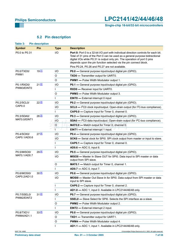
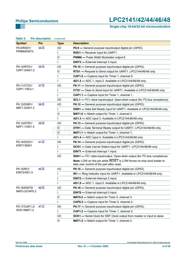
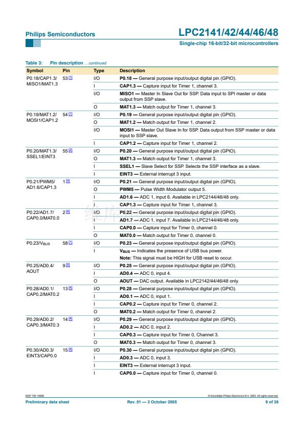
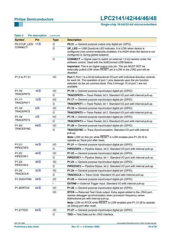
6.6 Pin connect block
The pin connect block allows selected pins of the microcontroller to have more than one
function. Con铿乬uration registers control the multiplexers to allow connection between the
pin and the on chip peripherals. Peripherals should be connected to the appropriate pins
prior to being activated, and prior to any related interrupt(s) being enabled. Activity of any
enabled peripheral function that is not mapped to a related pin should be considered
unde铿乶ed.
The Pin Control Module with its pin select registers de铿乶es the functionality of the
microcontroller in a given hardware environment.
After reset all pins of Port 0 and Port 1 are con铿乬ured as input with the following
exceptions: If debug is enabled, the JTAG pins will assume their JTAG functionality; if
trace is enabled, the Trace pins will assume their trace functionality. The pins associated
with the I
2
C0 and I
2
C1 interface are open drain.
9397 750 14985
漏 Koninklijke Philips Electronics N.V. 2005. All rights reserved.
Preliminary data sheet
Rev. 01 鈥?3 October 2005
14 of 38


 1
1
 2
2
 3
3
 4
4
 5
5
 6
6
 7
7
 8
8
 9
9
 10
10
 11
11
 12
12
 13
13
 14
14
 15
15
 16
16
 17
17
 18
18
 19
19
 20
20
 21
21
 22
22
 23
23
 24
24
 25
25
 26
26
 27
27
 28
28
 29
29
 30
30
 31
31
 32
32
 33
33
 34
34
 35
35
 36
36
 37
37
 38
38
