MITSUBISHI MICROCOMPUTERS
3822 Group
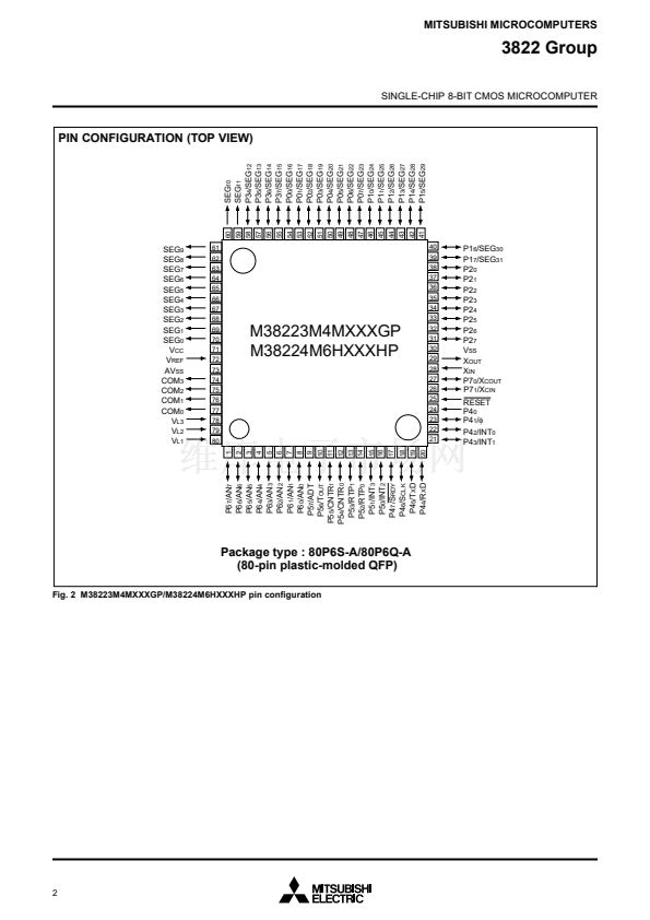
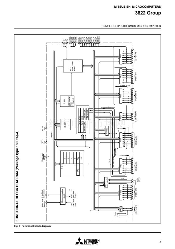
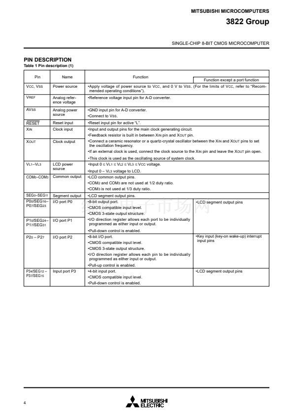
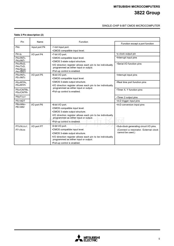
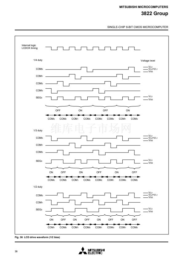
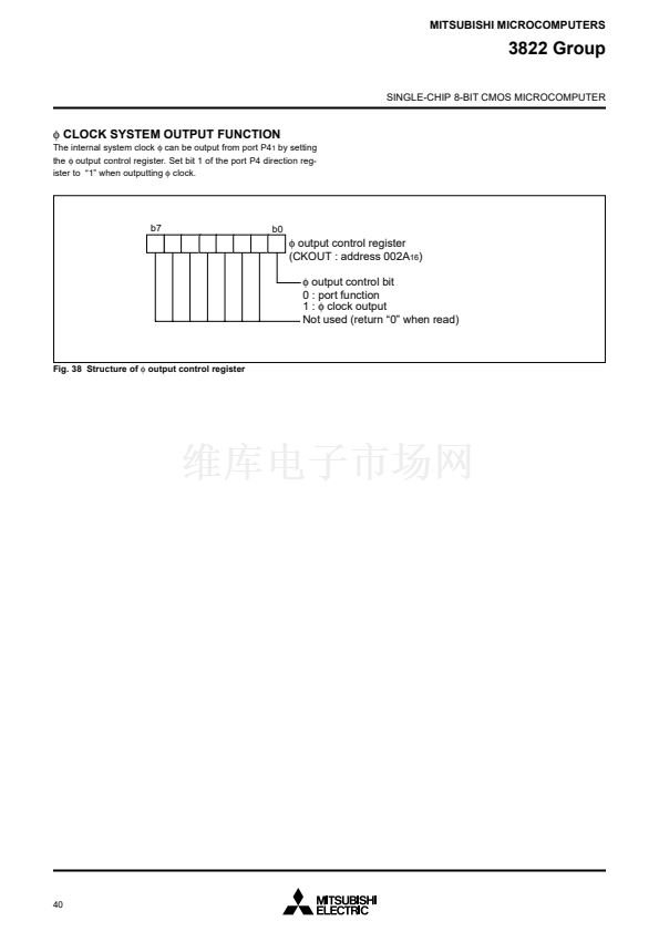
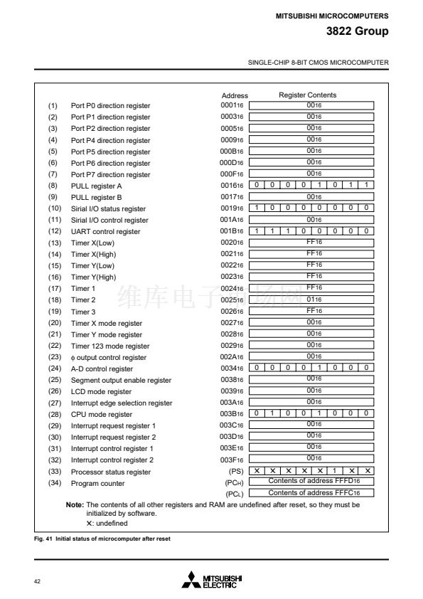
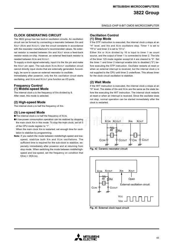
SINGLE-CHIP 8-BIT CMOS MICROCOMPUTER
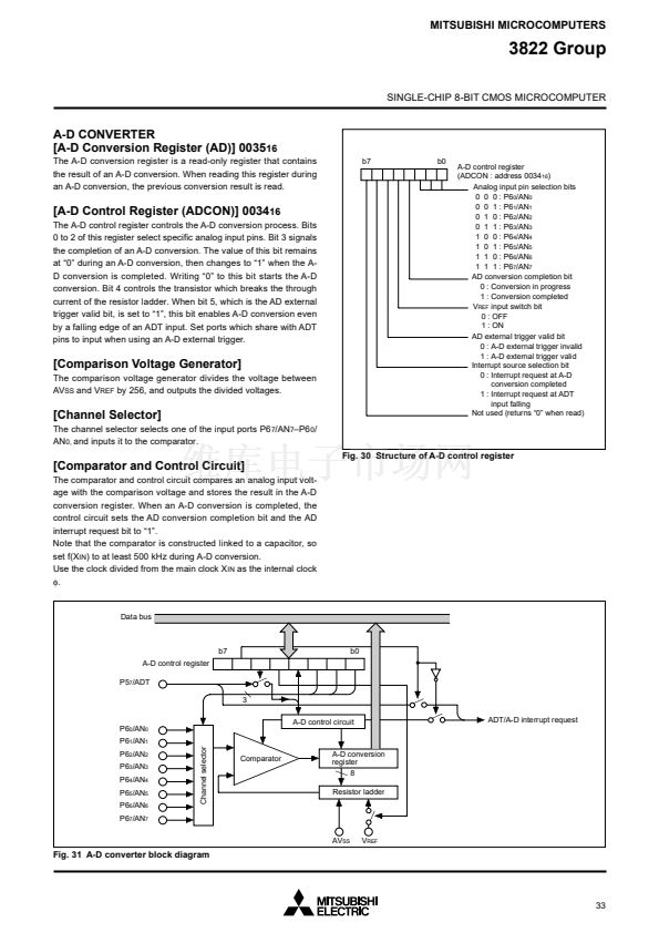
FUNCTIONAL DESCRIPTION
CENTRAL PROCESSING UNIT (CPU)
The 3822 group uses the standard 740 family instruction set. Re-
fer to the table of 740 family addressing modes and machine
instructions or the 740 Family Software Manual for details on the
instruction set.
Machine-resident 740 family instructions are as follows:
The FST and SLW instruction cannot be used.
The STP, WIT, MUL, and DIV instruction can be used.
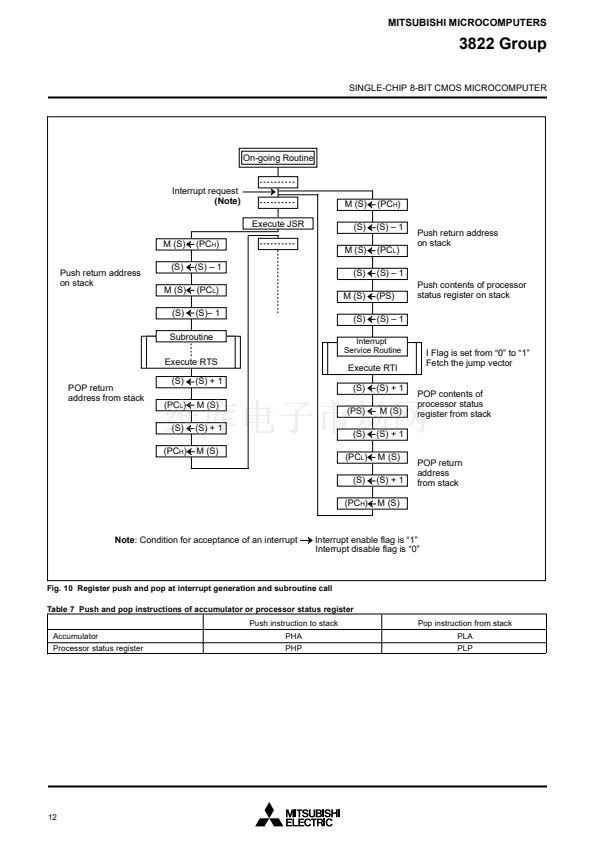
[Stack Pointer (S)]
The stack pointer is an 8-bit register used during subroutine calls
and interrupts. This register indicates start address of stored area
(stack) for storing registers during subroutine calls and interrupts.
The low-order 8 bits of the stack address are determined by the
contents of the stack pointer. The high-order 8 bits of the stack ad-
dress are determined by the stack page selection bit. If the stack
page selection bit is 鈥?鈥?, the high-order 8 bits becomes 鈥?0
16
鈥? If
the stack page selection bit is 鈥?鈥? the high-order 8 bits becomes
鈥?1
16
鈥?
The operations of pushing register contents onto the stack and
popping them from the stack are shown in Figure 10.
Store registers other than those described in Figure 10 with pro-
gram when the user needs them during interrupts or subroutine
calls.
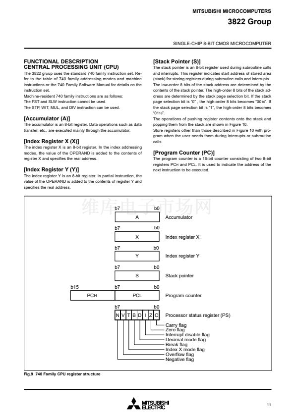
[Accumulator (A)]
The accumulator is an 8-bit register. Data operations such as data
transfer, etc., are executed mainly through the accumulator.
[Index Register X (X)]
The index register X is an 8-bit register. In the index addressing
modes, the value of the OPERAND is added to the contents of
register X and specifies the real address.
[Program Counter (PC)]
The program counter is a 16-bit counter consisting of two 8-bit
registers PC
H
and PC
L
. It is used to indicate the address of the
next instruction to be executed.
[Index Register Y (Y)]
The index register Y is an 8-bit register. In partial instruction, the
value of the OPERAND is added to the contents of register Y and
specifies the real address.
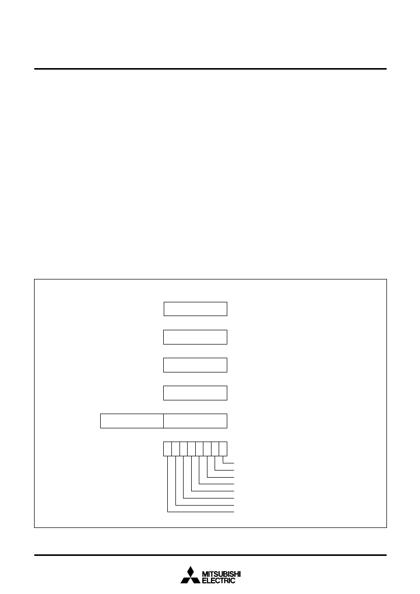
b7
A
b7
X
b7
Y
b7
S
b15
PC
H
b7
b7
PC
L
b0
Accumulator
b0
Index register X
b0
Index register Y
b0
Stack pointer
b0
Program counter
b0
Processor status register (PS)
Carry flag
Zero flag
Interrupt disable flag
Decimal mode flag
Break flag
Index X mode flag
Overflow flag
Negative flag
N V T B D I Z C
Fig.9 740 Family CPU register structure
11


 1
1
 2
2
 3
3
 4
4
 5
5
 6
6
 7
7
 8
8
 9
9
 10
10
 11
11
 12
12
 13
13
 14
14
 15
15
 16
16
 17
17
 18
18
 19
19
 20
20
 21
21
 22
22
 23
23
 24
24
 25
25
 26
26
 27
27
 28
28
 29
29
 30
30
 31
31
 32
32
 33
33
 34
34
 35
35
 36
36
 37
37
 38
38
 39
39
 40
40
 41
41
 42
42
 43
43
 44
44
 45
45
 46
46
 47
47
 48
48
 49
49
 50
50
 51
51
 52
52
 53
53
 54
54
 55
55
 56
56
 57
57
 58
58
 59
59
 60
60
 61
61
 62
62
 63
63
 64
64
 65
65
 66
66
 67
67
 68
68
 69
69
 70
70
 71
71
 72
72
 73
73
 74
74
 75
75
 76
76
 77
77
 78
78
